Партнерка на США и Канаду по недвижимости, выплаты в крипто
- 30% recurring commission
- Выплаты в USDT
- Вывод каждую неделю
- Комиссия до 5 лет за каждого referral
TECHNICAL MANUAL
TECHNICAL MANUAL
FOR THE
REMOVABLE INSECT SCREEN
Important:
This manual remains property of Hunter Douglas. Its content is strictly confidential and may not be reprinted, copied or reproduced in any form. The manual must be kept in its original form and should be returned to Hunter Douglas at their request.
The information in this manual has been provided for the benefit of our clients. It is based on general data concerning constructions, material characteristics and operational methods, as they were known to us at the time of publication, and is subject to alteration.
Unauthorized interpretation of information from this manual or any initiative taken on the basis of missing or incomplete data shall be at the user’s own risk, except with permission from Hunter Douglas. Working with data provided by Hunter Douglas and processing them does not release the user from his obligation to ensure the correct application of the purpose under consideration and check any specifications and diagrams, which are based on general data, against local circumstances.
Technical data are subject to alteration
© Copyright Hunter Douglas
® Legally registered trademark of Hunter Douglas
Patent applied for.
Chapter
1 - Introduction
2 - Parts list
3 - Assembly tools
4 - Cutting profiles
5 - Frame assembly
6 - Mounting options
7 - Packing
1 INTRODUCTION
1.1 Most important characteristics
1.2 Construction
1.3 Assembly
1.4 Installation
1.5 Measuring and ordering instructions
1.5.1 Fixed and hinged screens
1.5.2 Horizontally or vertically sliding screens
1.5.3 Ordering
1.1 Most important characteristics
- Colour coordinated hardware and profiles for white 0208 (RAL9016), off white 4419 (RAL9001), aluminium 7081 and brown 4950.
- RAL8014 brown also available, but with black hardware.
- A small profile (thickness only 11 mm) enables fixing even in limited spaces (e. g. if a shutter is present)
- A strong corner insert or profile connection and a slightly bowed profile ensure that the mesh will stay taut.
- Removable insect screens can be installed inside or outside the building. The following options exist:
- Hinged (on face, in recess, with top hanger)
- Sliding (horizontally and vertically sliding)
- Fixed directly to the window frame or reveal (using casement clips, plunger catcher or flanged profiles)
- A complete range of options enable the user to fix the screen in almost any situation.
- Very easy to assemble product with very low investment in tooling needed
1.2 Construction
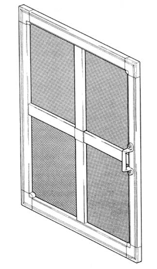
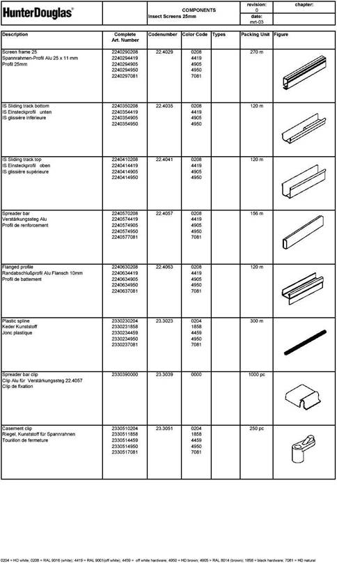
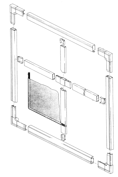
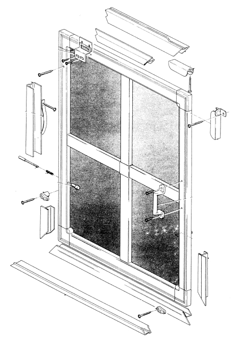
The basic removable insect screen consists of the following parts:
Frame
The frame section, 25x11 mm, is made of a closed aluminium tubular profile with a groove on one side to hold the mesh taut by means of a plastic spline. The profile has been double stove enameled according to Hunter Douglas coil coating process, precede by a degreasing and chromatizing treatment for maximum bond between paint and metal. The frame section is slightly bowed, which will keep the mesh taut.
Cross profile
For screen sizes over 1 meter in width and/or drop, additional cross profiles are placed in the center. The cross profile, 20 x 8 mm, is a closed aluminium tubular profile with the same finish as the frame section.
Corner inserts
The corner insert connects the frame sections.
Spline
The spline has a knurled circumference (lengthwise). Its diameter has been designed to fit exactly into the frame groove which holds the mesh taut.
Fiberglass mesh
The fiberglass mesh is coated with synthetic material which ensures that water, oil, grease, corrosion etc. will not affect the mesh.
1.3 Assembly
The removable insect screen is very simple to assemble. Assembly staff requires no specific training. The assembly will be explained in this manual by means of “no-text pictures”. The total time needed for assembly of a product of average size (1 meter by 1 meter) is approximately 10 minutes.
Required tools
No specific tools are required to assemble removable insect screens. If necessary, Hunter Douglas will supply a length stop and spline roller. You should provide a drill, screwdriver set, sawing machine and other small tools yourself.
1.4 Installation
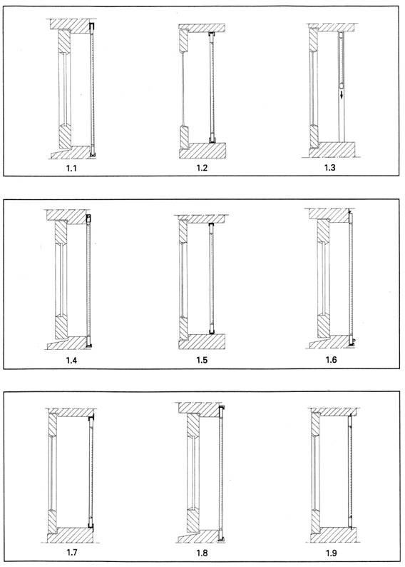
The removable screens can be fixed to the window frame or reveal in three different ways; by sliding, by hinging or by fixing directly to the window frame or reveal. Either on the inside or on the outside.
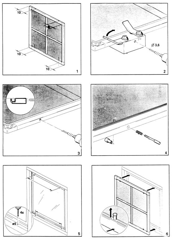
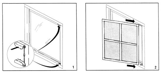
· the sliding screens can be fixed in three different ways: horizontally sliding, fix on face (fig. 1.1); horizontally sliding, fix in recess (fig. 1.2); vertically sliding, fix in recess (fig. 1.3)
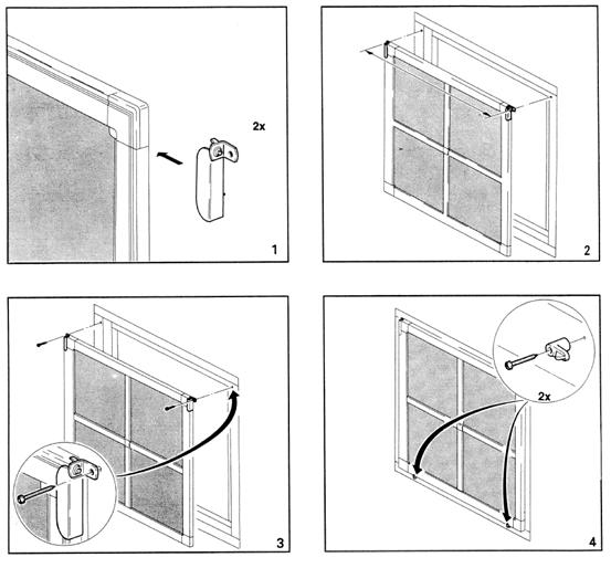
· the screens can be hinged in three different ways: hinge on face (fig. 1.4); hinge in recess (fig. 1.5); top hanger (fig. 1.6)
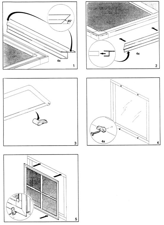
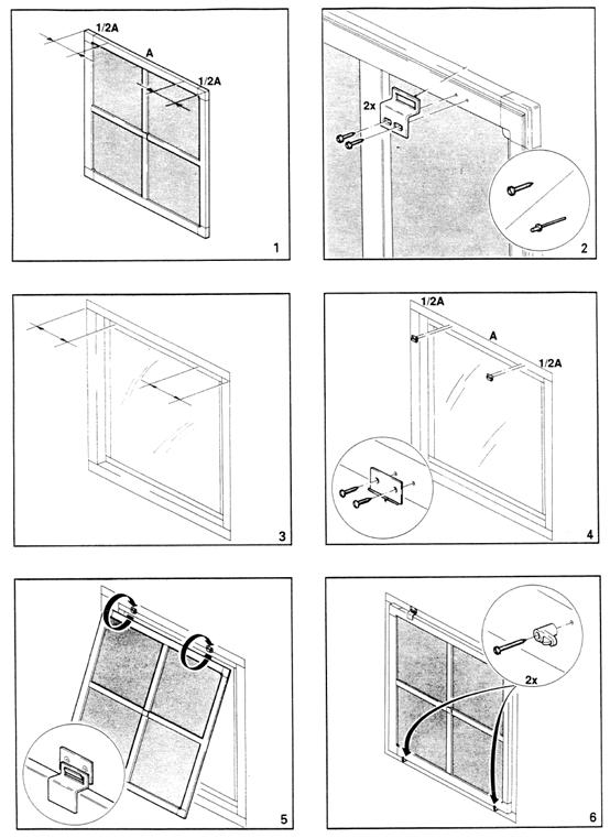
· the screens can be fixed in three different ways to the window frame or reveal: flanged profile (fig. 1.7); casement clip (fig. 1.8); plunger catch (fig. 1.9)
Maximum dimensions
Maximum width : 2200 mm
Maximum height : 2200 mm
Maximum surface : 2.50 m2
1.5 Measuring and ordering instructions for removable insect screens
When measuring a screen, bear the following in mind:
1.5.1 Fixed and hinged screens
Fixing methods
State the fixing method explicitly on the order form. Always leave ample space next to the screen for attachment of the fixing parts.
Obstacles
When measuring take into consideration any obstacles (like handles etc.) which might obstruct the functioning of the screen.
Dimensions
When measuring state the correct dimensions as follows:
- in recess : smallest height and smallest width of the recess
- on face : dimensions of the screen
The manufacturer is only able to produce screens using the dimensions given by the measurer. Except for a standard recess deduction the manufacturer cannot take into consideration reductions for rails, handles etc.
Cross profiles
Cross profiles are used for screens wider than 1 meter. If both sides of the screen are longer than 1 meter 2 cross profiles are applied crosswise. Please state required exemptions.
Details
State all details concerning fixing, additional special profiles (e. g. angle profiles, insert pieces, etc.) on the order form. If necessary include a small sketch.
1.5.2 Horizontally or vertically sliding screens
Installation
Always state on the order form:
· whether you want to install the screen “on face” or “in recess”;
· whether you want single, double or triple screens;
· whether you want horizontally or vertically sliding screens;
· the number of handles to be supplied;
· the number and length of the tracks supplied.
Tracks
In case of horizontally sliding screens the tracks should not divert more than 7 mm. In case of vertically sliding screens the difference should not be more than 3mm. If the tracks are further apart than these tolerances, the tracks are to be raised until they run parallel.
Dimensions
When measuring state the correct dimensions (i. e. the dimensions with all the reductions subtracted) of the screen only. The manufacturer is only able to produce screens using the dimensions given by the measurer. The manufacturer cannot take into consideration reductions for tracks, springs, etc.
Details
State all the details concerning fixing, additional special profiles (e. g. angle profiles, insert pieces, etc.) on the order form. If necessary include a small sketch.
1.5.3 Ordering
When placing an order, state the following:
· screen type (sliding, hinged or fixed directly)
· screen colour (white, off white, brown, aluminium)
· recess size if the screen is to be installed in recess;
shortest length if the screen is to be installed in recess;
shortest width if the screen is to be installed in recess;
· finished screen size if the screen is to be installed on face.
· special requirements: e. g. flanged profiles.
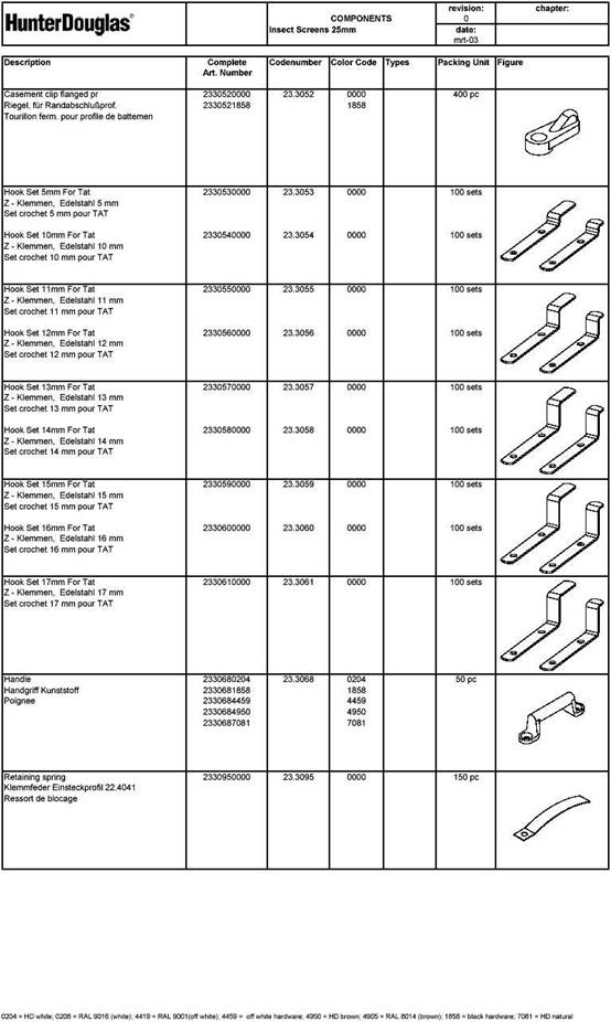
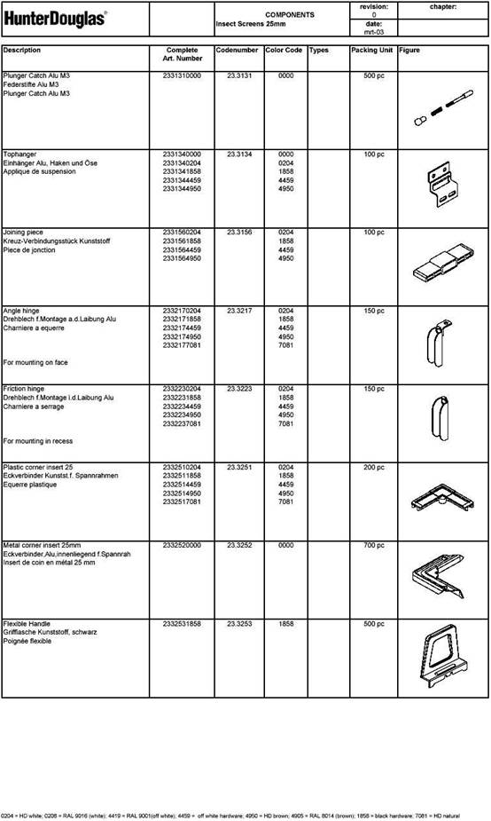
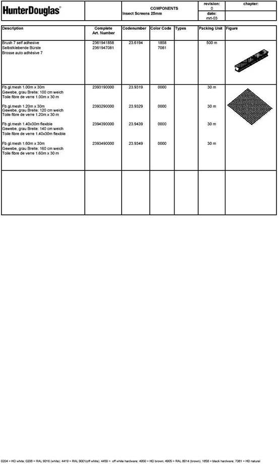
2 Parts list
3 Assembly tools
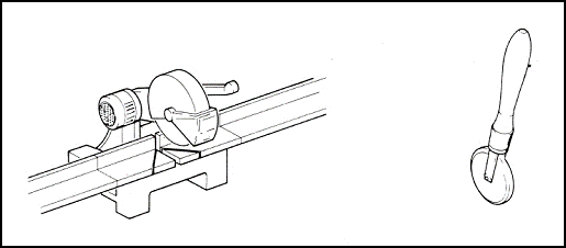
Sawing machine with 45 cutting possibility : purchase locally
Spline roller : purchase locally or contact
Hunter Douglas
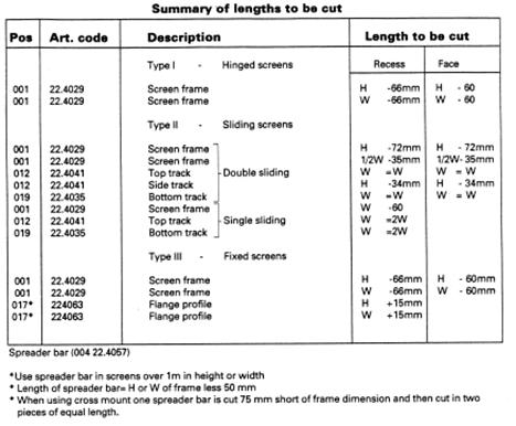
4 Cutting profiles
Type I - Hinged screens
Type II - Sliding screens
Type III - Fixed screens
Fig. 1.1 - In Recess
Fig. 1.2 - On Face
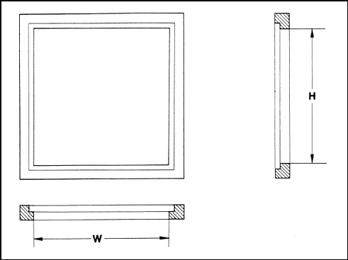
Fig. 1.1
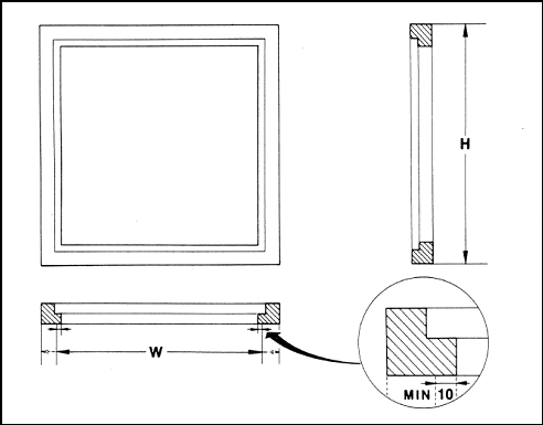
Fig. 1.2
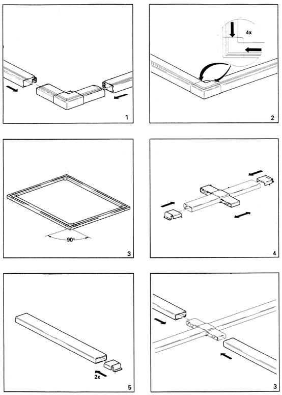
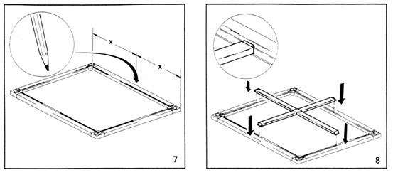
5 Frame assembly
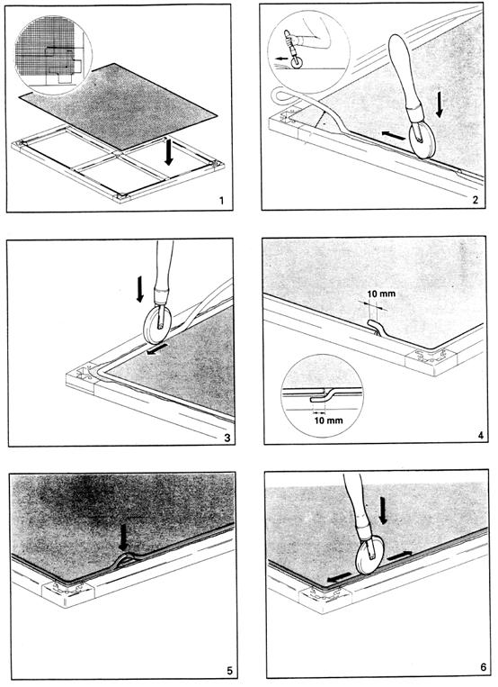
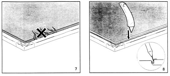
6 Mounting fiberglass mesh
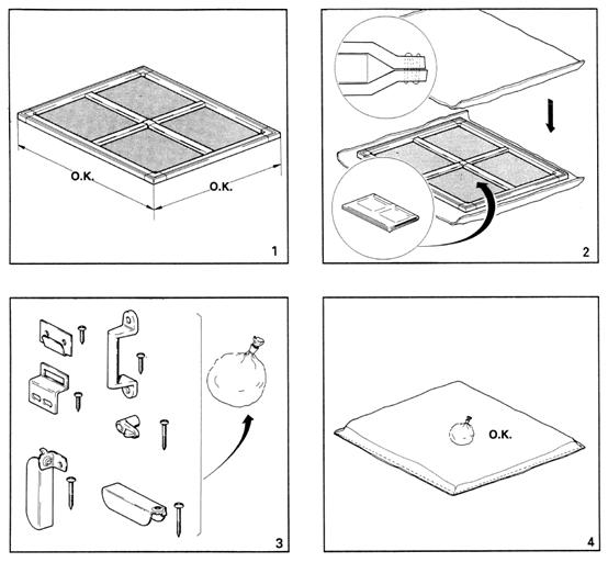
7 Mounting options
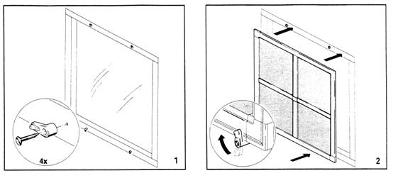
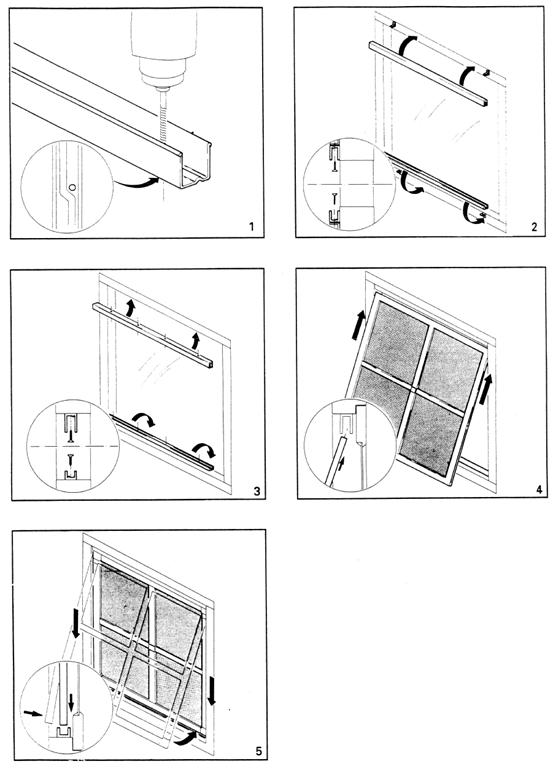
8 Packing