
Партнерка на США и Канаду по недвижимости, выплаты в крипто
- 30% recurring commission
- Выплаты в USDT
- Вывод каждую неделю
- Комиссия до 5 лет за каждого referral
Элементы для схемы на рис 11.6 :
R1=47K, R2=100K(H4), Р3=47к, R4=39K. R5=5.6K, Рб=100к(ВЧ), R7=180K, R8=33K, R9=3.9K, R10=1K,
С1=39н, С2=ЗОмкФ-100мкФ, СЗ=5мкФ-20мкФ, С4=2.2н, С5=2.2н. Сб=ЗОмкФ-100мкФ:
Т1 - КТ3102, КТ315 или аналогичные.
На рис 11.7 представлен пример схемы двухполосного регулятора тембра НЧ и ВЧ для УНЧ на ОУ. Данной электронной схеме предшествует каскад на ОУ. Это обеспечивает низкое выходное сопротивление предшествующего каскада и нормальную работу данного регулятора. Для повышения устойчивости работы схемы (на ВЧ) целесообразно эашунтировать выводы питания ОУ конденсаторами 0.1 мкФ, например, типа КМ6. Конденсаторы подключаются максимально близко к ОУ.

Рис. 11.6. Схема двухполосного регулятора тембра (НЧ, ВЧ) на транзисторе.

Рис. 11.7. Схема двухполосного регулятора тембра (НЧ, ВЧ) на ОУ.
Элементы для схемы на рис.11.7:
R1=11K, R2=100K(H4),R3=11K, R4=11K, R5=3.6K, R6=500K(B4),R7=3.6K, R8=750;
С1=005мкФ, С2=0.05мкФ, СЗ=0.005мкФ, С4=0.1 мкф-0.47мкф, С5=0.1 мкф-0.47мкф;
ОУ - 140УД12,140УД20, 140УД8 или любые другие ОУ в типовом включении и желательно с внутренней коррекцией;
Трехполосный регулятор тембра дает лучший результат подавления помех, чем двухполосный регулятор.
На рис.11.8 представлен пример схемы трехполосного регулятора тембра НЧ, СЧ и ВЧ для УНЧ на ОУ. Данной электронной схеме предшествует каскад на ОУ. Это обеспечивает низкое выходное сопротивление предшествующего каскада и нормальную работу данного регулятора. Для повышения устойчивости работы схемы (на ВЧ) целесообразно зашунтировать выводы питания ОУ конденсаторами 0.1 мкФ Конденсаторы подключаются максимально близко к ОУ.
Элементы для схемы на рис.11.8 :
R1=11K, R2=100K(H4), R3=11K, R4=11K, R5=1.8K, Р6=500к(ВЧ), R7=1.8K, R8=280, R9=3.6K, R10=100K (СЧ), R11=3.6K;
С1=0.05мкФ, С2 - отсутствует, СЗ=0.005мкФ, С4=0.1 мкф-0.47мкф, С5=0.1 мкф-0.47мкф, С6=0.005мкФ, С7=0.0022мкФ, С8=0.001мкФ;
ОУ - 140УД8, 140УД20 или любые другие ОУ с внутренней коррекцией (желательно) и в типовом включении.
Значительно лучший результат подавления помех, чем при двухполосном и трехполосном регуляторе тембра, дает использование в составе УНЧ многополосного регулятора частотной характеристики усилителя - эквалайзера. Эквалайзер - многополосный регулятор тембра дает возможность коррекции АЧХ с целью эффективного подавления помех.
На рис.11 9 представлен пример схемы 11-полосного эквалайзера на ОУ. Данной электронной схеме предшествует каскад на ОУ. Это обеспечивает низкое выходное сопротивление предшествующего каскада и нормальную работу данного регулятора. Для повышения устойчивости работы схемы (на ВЧ) целесообразно зашунтировать выводы питания ОУ конденсаторами 0.1 мкФ, например, типа «Мб. Конденсаторы подключаются максимально близко к ОУ
Частотный корректор содержит 11 полосовых фильтров второго порядка, каждый из которых состоит из ОУ и четырех пассивных элементов R1, R2, С1, С2. Отношение резонансных частот соседних фильтров выбрано равным значению 1.86. Благодаря этому суммарная ФЧХ данного корректора получается линейной. Эквивалентная добротность фильтров Q равна 1.25. Это обеспечивает наиболее оптимальную АЧХ.
Сигналы с выхода каждого полосового фильтра, входящего в состав корректора АХЧ, поступают на сумматор на ОУ (А2). Подъем или спад усиления в полосе пропускания каждого фильтра определяется сопротивлением резисторов R3, R4 и составляет от -12дб до +12дб.
Переменные резисторы R4, с помощью которых осуществляется коррекция АЧХ - подъем и спад усиления в частотных диапазонах фильтров, должны иметь линейную характеристику Их номиналы могут отличаться от

Рис.11.8. Схема трехполосного регулятора тембра (НЧ, СЧ, ВЧ) на ОУ.
рекомендуемых, но тогда потребуется соответствующее изменение номиналов R3 и R5: коэффициент усиления ОУ А1 по каждому каналу равен R5/ (R3+R4).
Элементы для схемы на рис. 11.9:
Фильтр | Резонансная частота. Гц | R1, к()м | R2, к0м | С1=С2 | R3, к0м | R4, к0м | |
1 | А | 30 | 12 | 75 | 0.18 мкф | 3.3 | 47 |
2 | В | 56 | 12 | 75 | 0.1 мкф | 3.3 | 47 |
3 | С | 104 | 12 | 75 | 0.047 мкф | 3.3 | 47 |
4 | D | 194 | 12 | 75 | 0.027 мкф | 3.3 | 47 |
5 | E | 360 | 12 | 75 | 0.015 мкф | 3.3 | 47 |
6 | F | 671 | 12 | 75 | 7500 | 3.3 | 47 |
7 | (1 | 1249 | 12 | 75 | 3900 | 3.3 | 47 |
8 | Н | 2325 | 12 | 75 | 2200 | 3.3 | 47 |
9 | I | 4328 | 12 | 75 | 1200 | 3.3 | 47 |
10 | .1 | 8057 | 12 | 75 | 560 • | 3.3 | 47 |
11 | К | 15000 | 12 | 75 | 330 | 3.3 | 47 |
Остальные элементы :
R5=3K,
ОУ - 140УД8, 140УД12, 140УД20 или любые другие ОУ с внутренней коррекцией (желательно) и в типовом включении.
Альтернативой трубе, существенно повышающей направленность микрофона и снижающей акустические помехи, может служить параболический концентратор звука - параболический рефлектор. При прослушивании источника звука. находящегося на значительном расстоянии. микрофон помещается в фокус рефлектора. Очевидно, что размеры. качество поверхности и. конечно, параметры микрофона и усилителя влияют на конечный результат. Из технической литературы известны примеры регистрации с помощью подобных конструкций направленных микрофонов звуковой информации очень низкой интенсивности. например, тиканье часов на расстоянии в несколько метров.
Микрофон с параболическим рефлектором и чувствительный, малошумящий усилитель являются стандартными средствами, используемыми. например, учсными-орнитолагами при дистанционной записи птичьих звуков. Кстати, вот и опять пример двойного использования электронных средств: благородное - наука, техника, связь, быт, иное - промышленный шпионаж с применением разнообразных электронных средств или. если угодно. - коммерческая разведка,
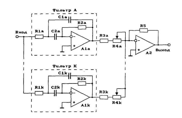
Рис. 11.9. Схема 11 - полосного эквалайзера (корректора АХЧ) на ОУ.
Active Tone Controls.
http://www. /electronic/funwithtubes/Amp-Tone-A. html
Now we are up to active tone controls. They are defined as needing an amplifier to work properly. They also use linear controls. The advantage of linear controls is they always have half resistance at half rotation. Some audio taper controls do not have 10% resistance at half rotation. With active controls it is easier to be sure that setting the controls to center of rotation will give tone flat. It is still the basic Baxandall circuit but it is in the feedback loop of an amplifier. Transistor designers jumped on this one early on because gain is so easy to come by in a small space as compared to tubes. It is doable with tubes but might require one extra 12AX7 per channel as compared to passive circuits. Many people might say that the improved symmetry of response curves is worth it. I would be inclined to agree.
The Brimar Circuit.
Brimar was the name of a tube manufacturer in England who came up with the circuit shown in Figure 11.
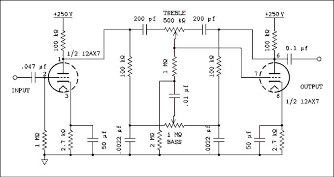
Figure 11 Brimar Tone Control Circuit.
For a verbal description click here.
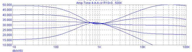
Figure 12 Frequency Response Showing a Flaw.
For a verbal description click here.
This circuit looks quite elegant on paper, or computer screen, but the frequency response shows a real problem. Look at the flat gain in the bass portion and compare it with the same curve in the treble region. I imagine this would give the amplifier a rather dim sound, the opposite of bright. The tube on the right has a lot of feedback around it but the one on the left is operating completely open loop and at full gain with a bypassed cathode resistor. The output resistance of this stage is the 100 k ohm load in parallel with the plate resistance of the tube (12AX7) which is 80 k ohms. That works out to 44 k ohms. The graph in Figure 15 below shows how the impedance of a similar circuit varies with frequency. This problem could be cured by adding a cathode follower to each amplifier stage.
In spite of its other shortcomings you will note a much improved symmetry of the frequency response over the open-loop Baxandall tone control. This makes for a much smoother cut and boost as well as identical spectra for both.
The circuit has 33 dB of gain at tone flat and 100 cycles. Removing the cathode bypass capacitor only lowers this figure to 25 dB. That's still a lot of gain to stick into the middle of a preamp. I have never owned a commercial preamp but my design approach would be to give it 10 dB of gain with the volume control set to maximum. The argument being, the output stage should not be driven into clipping even at maximum volume and tone setting. Most sources deliver about 0.7 volts RMS which is about 2 volts peak to peak. 10 dB will increase this to 6.3 volts peak to peak. Granted that's not much for a tube amplifier but if the owner decides to crank in full bass boost at 15 dB more we are up to 35 volts P-P. That's certainly at a level which could increase distortion if not taking it to the point of clipping. So dropping this control into the middle of a preamp would increase the output to a whopping 623 volts peak to peak. If you are still awake you will remember that I put in an initial gain of 10 dB. If we take that out and just have the tone control with the cathode bypass removed, 25 dB of gain from the starting point of 2 volts P-P gives us 36 volts and then the 15 dB of bass boost puts the overall gain at 40 dB which will give 200 volts P-P from our original 2 volts P-P. No matter how you slice it, it seems to be too much gain. A figure of 10 dB gain plus 15 dB of bass boost will give 36 volts P-P from our original 2 v P-P. So I think I'll stick to my 10 dB overall gain figure.
Putting the Baxandall Inside a Feedback Loop.
The curves of the open loop Baxandall circuit may seem a little less than perfect. I would be the first to grant that it probably would be impossible to hear the difference. However, I am somewhat of a perfectionist so it would be nice if a circuit could be developed that behaved better than the passive circuits above. It seems that if we put the passive circuit inside of the feedback loop of an amplifier it will give curves that look much better.
The Principle of an Inverting Amplifier.
To understand how an active tone control works we must digress a little to study inverting amplifiers. The inverting amplifier has several unique features but the one that is important to us is the ability to employ feedback to set it to less than unity gain. The noninverting amplifier can be set to unity by strapping the output to the inverting input. The gain can't be set any lower than that. The inverting amplifier, in Figure 13 (a) below, does not have this limitation.

Figure 13 (a) Showing How Feedback Sets Gain.
(b) Showing Tone Control in Feedback Loop.
For a verbal description click here.
In the circuit of Figure 13 (a) , a generalized amplifier has feedback applied from output to inverting input through R2. The input signal is applied through R1. If the gain of the amplifier is large the voltage from the inverting input to ground will be small. That means the currents through R1 and R2 are set mainly by the magnitude of the input and output voltages. If the input impedance of the amplifier is large the current flowing through the input terminal will be very small. Thus we can say that the current in R1 is the same as the current in R2. We can write the equations,
VIN = I1 x R1 and VOUT = I2 x R2
But,
I1 = I2
Because the currents in R1 and R2 are equal and in the same direction and VIN is on the left end of R1 and VOUT is on the right end of R2 the input and output voltages have to be of opposite signs.
Lets try some simple logic on that one. Now, we must be sure to say exactly what we mean and mean exactly what we say. In part A of Figure 13 above, the term, input refers to the left end of R1. Output refers to the right end of R2 which is also the amplifier output. Inverting input refers to the point where R1 and R2 connect to the amplifier. Remember that the voltage at the inverting input of the amplifier is very small. Lets call it zero for the sake of argument. If you place a positive voltage on the input the only way to get zero at the inverting input is for the output to be negative. The inverting input is a tube grid so it is an open circuit. You can't have both ends of the resistor string be negative and have the middle be zero. They must always be opposites. Now, if the input signal is AC the output will be AC of the opposite phase. And that, Virginia, is why its called an inverting amplifier.
We are going to solve the two equations above for I, since they are equal, and set them equal to each other. But because of the sign difference between input and output we have to sneak in a minus sign.
VIN / R1 = - VOUT / R2
Rearranging gives,
VOUT / VIN = - R2 / R1
Of course VOUT / VIN is the gain. If R2 is larger than R1 the gain will be greater than unity. If R2 is less than R1 the gain will be less than unity.
One more little fact about an inverting amplifier is that the inverting input acts like a low impedance point. If the gain of the amplifier is very high, say one million, the input will act like a dead short to ground. The reason for this is, what ever the input voltage does the output voltage will be adjusted to the opposite sign and the necessary magnitude to keep the inverting input at zero. There is current flowing but no, or very little, voltage and that spells low impedance. In practical operational amplifiers the inverting input point, or summing node, is often referred to as a virtual ground. For more information on the subject of feedback amplifiers refer to Chapters 5 and 6 of my textbook Electronics for Physicists. The book is on another web site so use your back button to return here.
Now look at the schematic of Figure 13 (b) above, in which the Baxandall circuit has taken the place of R1 and R2. Strange as it may seem there is virtually no current flowing in the 15 k ohm resistor or the 6.8 k ohm resistor.* Looking back at part A, the current due to signal is flowing through R1 and R2. There is essentially no current flowing in the vertical line connecting the junction of the two resistors to the inverting input. A resistor could be placed in this line with no measurable effect on the performance of the amplifier. The one restriction would be that the added resistor must be much less than the input impedance of the amplifier. In part B, the input resistance of the amplifier is much greater than the 15 k ohm resistor. At frequencies where the reactance of the 0.001 uf capacitor becomes large the treble control is no longer having any effect so this is of no consequence.
* This statement is true only if the two controls are set to the same point. If there is a difference the circuit becomes more difficult to analyze and we will leave such analysis for another time and place when and where everyone understands how to use the j operator.
The wipers of the pots are at zero potential so if they are set at center, the connection points on the left and right are at the same potential and opposite phase. This is equivalent to R1 = R2 in part A. The gain is unity for all frequencies. If the wipers are moved to the left this is equivalent to R1 growing smaller and R2 growing larger. This will increase the gain but only for lows and highs. The mid range, around 1,000 cycles will be little effected. Moving the wipers to the right of center will cause the gain to be less than unity and the highs and lows will be cut.
If the bass control is moved to the left while the treble control is left at the center, the unbalance will drive current through the 15 k ohm resistor at low frequencies. The effect will be that of decreasing R1 and increasing R2. The gain will be increased for low frequencies. At mid and high frequencies the two 0.1 uf capacitors will keep the circuit balanced, R1 = R2, and the gain for these frequencies will remain at unity.
When the bass pot is returned to center and the treble pot is moved to the left the wiper becomes unbalanced for all frequencies but only the highs are coupled to the inverting input through the 0.001 uf capacitor. A circuit with two capacitors, one on each side of the treble pot performs better and is easier to understand. I have not run a simulation on the circuit in part B so I can't say how well it performs. It could be used with op amps or transistorized gain blocks but it's impedance is too low to be used with tubes. Well, maybe with cathode followers.
A Tone Control You Can Love.
Figure 14 shows the tone control that I think has the best compromise between performance and tube count. Yes Virginia, everything is a compromise. It uses only two triodes per channel, one 12AX7 or your choice of other hi mu triodes, and it has a nice symmetrical looking frequency response curve. Its gain when set to flat is about -1 dB which is close enough to unity to not cause overload problems in a preamp or integrated amplifier. You could transplant the tube stages from Figure 18 below if inclined. The performance would be slightly improved.
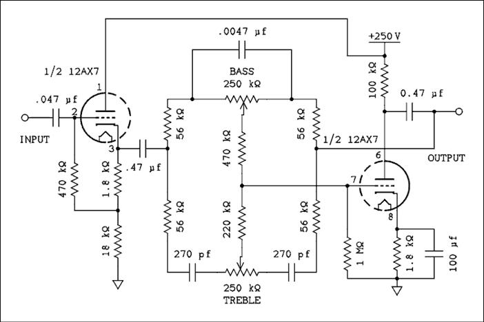
Figure 14 Practical Tone Circuit Using One 12AX7 Per Channel.
For a verbal description click here.
The pots are linear taper and the center of rotation is tone flat. Moving the wipers to the right on the diagram is cut, which would be the counter clockwise position, and to the left is boost, the clockwise end of the control. All resistors are 1/4 watt although you may use 1/2 watt if you prefer. The 100 k ohm resistor from pin 6 of the 12AX7 should be a 1/2 watt in any case. The 0.47 uf capacitor on the left may have a voltage rating as low as 200 volts but the one on the right should be a 630 volt. The voltage rating of the 0.047 uf depends on what is connected to the input of the circuit. If it is the plate of a tube the voltage should be 630 volt. If the wiper of a pot a 200 volt would be fine. The three capacitors in the tone circuit don't need to be anymore than 50 volts although there is no harm in going much higher if they are all you can get.
Unlike the passive circuit this one uses a single capacitor across the bass pot instead of two from each end to wiper. If this were to be done in a passive circuit setting of the bass control would alter the amount of treble boost or cut. The virtual ground of the amplifier grid effectively isolates the bass and treble circuits and the interaction amounts to about 1/100 of a dB.
This was not done to save capacitors. Connecting two capacitors from wiper to each end causes the resistance in parallel with the capacitor to change as the bass pot is turned. This causes the corner frequency of the bass boost and cut to change depending on the setting of the pot. This effect is clearly visible in Figure 10. Figure 15 looks much better as the breakpoints on the bass curves remain constant regardless of the setting of the control.
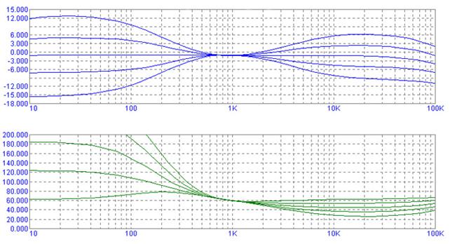
Figure 15 Graph Showing Frequency Response, and Drive Impedance of Circuit of Figure 14.
For a verbal description click here.
The graph at the bottom in green is k ohms of input impedance of the tone circuit. The measurement was made by inserting a current controlled voltage source in series with the 0.47 uf capacitor on the left. The bottom line is full boost, the next one up is half boost and the highest one to be completely on the graph is flat. Now you can see the reason for the gain variation in the Brimar circuit above. With an impedance of 80 k ohms at 100 cycles and 45 k ohms at 10 kc it's no wonder why a cathode follower is required to drive the circuit. The amplifier on the right would have the same trouble if it didn't have so much feedback around it. It's open-loop gain does change but not enough to cause any significant problems.
Baxandall Tone Control Using LM833: The Circuit Schematic Diagram and The Formula
http://www. /general/Baxandall_Tone_Control_Using_LM833__The_Circuit_Schematic_Diagram_and_The_Formula_3726.html
This circuit is similar to our previous tone control circuit, a bass-treble tone control circuit, but here we present the formula for design your tone control’s custom frequency response. Here is the schematic diagram and formula of the tone control circuit:
Almost all op-amp type can be used, as long as they have high input impedance, much higher than the resistors selection. The resistor should be much lower value than the capacitor’s leakage resistance equivalence value. Finally, using the formula shown in the above figure, we can design custom frequency response for our own Baxandall tone control circuit. [Schematic diagram source: National Semiconductor Application Notes]
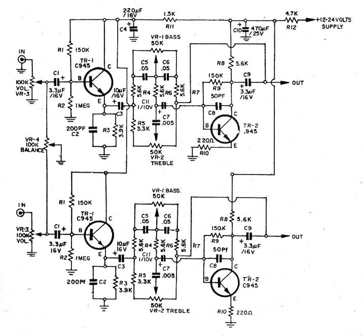
2 Transister (C945) tone control Stereo.
http://electrocircuitschema. *****/2007/05/2-transister-c945-tone-control-stereo. html
This circuit Tone Control Stereo, 2 Transister : C945 = 2 part.
Supply Volt min 12V <80mA.
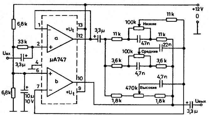
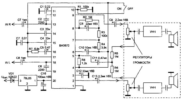
Активный двухканальный фильтр на ВА3870 (MEGA BASS)
http://softlink. /publ/12
ИМС ВА3870 представляет собой активный двухканальный фильтр, производящий специальную обработку стереосигнала, создавая более объемный и «прозрачный» звук.
Фильтр подключается перед регуляторами громкости, с движков которых снимается сигнал обратной связи (DET).
Следующая схема регулятора тембра «Темброблок на операционном усилителе» взята из журнала Радио №10, 1982 стр 58


|
Из за большого объема этот материал размещен на нескольких страницах:
1 2 3 |
