

Партнерка на США и Канаду по недвижимости, выплаты в крипто
- 30% recurring commission
- Выплаты в USDT
- Вывод каждую неделю
- Комиссия до 5 лет за каждого referral
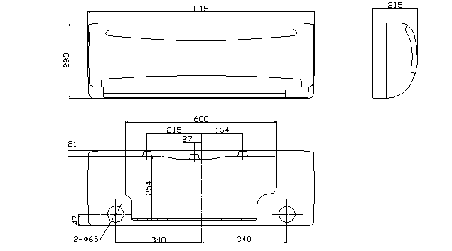
4.1 Indoor unit dimension
a) Indoor unit 9K
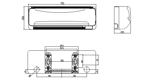
b) Indoor Unit 12K
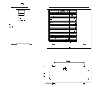
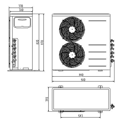
4.2 Outdoor unit dimension
a) Outdoor unit 18K/21K
b) Outdoor unit 27K/30K
5. Refrigeration cycle diagram
“1 drives 3 system” is made up of one “1 drive 1 system” and one “1 drive 2 system”.
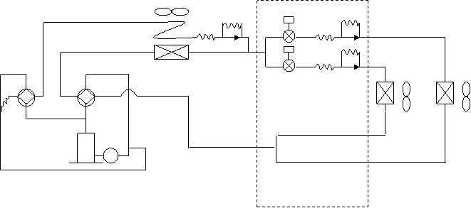
PMV2 |
SV2 |
PMV1
SV1 |
2# |
1# |
T2 |
T1 |
refrigeration distributor |
1 drive 2 system
SV1:Primary four-way valve SV2:Secondary four-way valve PMV1,PMV2:Electronic expansive valve T1,T2:Indoor pipe temperature sensor
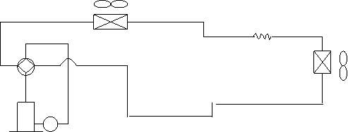 |
Condenser
Four-way valve
Evaporator
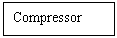
Compressor
1 drive 1 system
Notice:For 1 drives 2 system, there are two individual refrigerant circuit and two compressors, but for the 1drive 2 system in the 1 drive 3 system, there is only one refrigerant circuit and only one compressor.
6. Wiring diagram
6.1 Indoor unit
Indoor unit
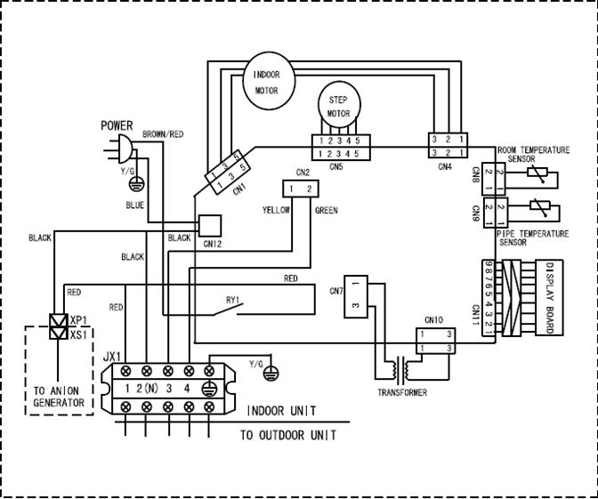
Glory indoor unit
6.2 Outdoor unit
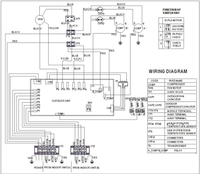
For 1 drive 2 outdoor unit
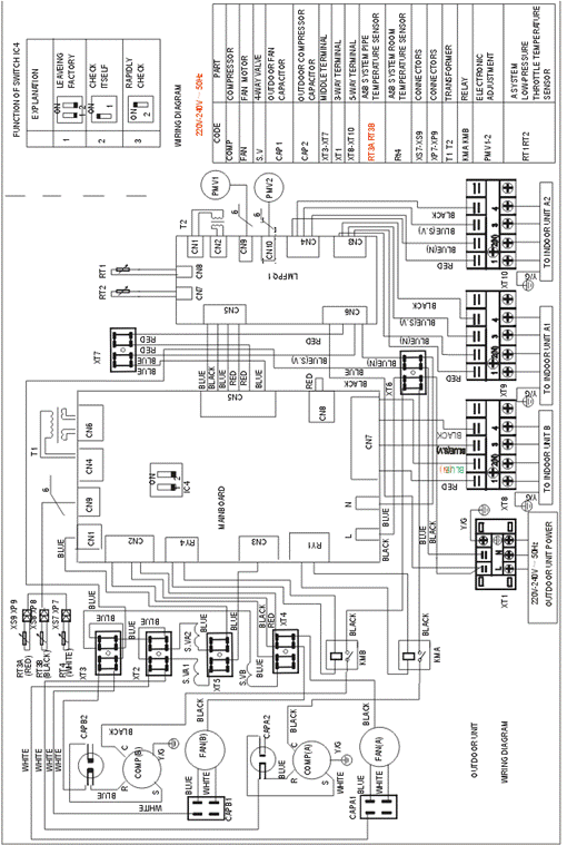

For 1 drive 3 outdoor unit
7. Troubleshooting
7.1 Indoor unit
Failure phenomenon | Operation lamp | Timer lamp |
Indoor fan speed has been out of control for over 1 minute | ☆ | X |
Indoor room temp. Sensor or evaporator temp. Sensor is open circuit or short circuit | ☆ | On |
EEPROM error | On | ☆ |
Cross zero signal error | ☆ | ☆ |
r Extinguish
☆ Flash at 5Hz
On Light
7.2 Outdoor unit (on mainboard)
7.2.1 1 drive 2
Failure phenomenon | LED1 | LED2 | LED3 |
Stand by | ☆ | ☆ | ☆ |
High temp. protect of condenser | ☆ | ☆ | |
Temp. sensor in condenser 1 is open circuit or short circuit | ☆ | ||
Temp. sensor in condenser 2 is open circuit or short circuit | ☆ |
☆ Flash at 2Hz
7.2.2 1 drive 3
Failure phenomenon | LED1 | LED2 | LED3 | Sensor in outdoor unit |
High temp. protect of condenser | ☆ | ☆ | RT3B or RT3A | |
RT3A sensor is open circuit or short circuit | ☆ | RT3A | ||
RT4 sensor is open circuit or short circuit | ☆ | RT4 | ||
RT3B sensor is open circuit or short circuit | ☆ | RT3B |
☆ Flash at 2Hz
7.3 Diagnostic chart
7.3.1Indoor fan speed has been out of control for over 1 minute
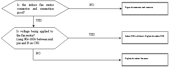

7.3.2 Indoor room temp. sensor or evaporator temp. sensor is open circuit or short circuit
7.2.3 EEPROM error


7.2.4 Cross zero signal error


7.2.5 High temp. Protect of condenser
When outdoor pipe temp. is more than 65°C, the unit will stop, and unit runs again when outdoor pipe temp. less than 52°C.
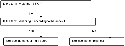

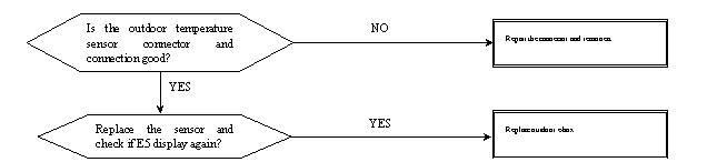
7.2.6 Temp. Sensor in condenser is open circuit or short circuit

8 Electronic functions
8.1 Electric Control working environment
8.1.1 Input voltage: 175~253V
8.1.2 Input power frequency: 50Hz/60Hz
8.1.3 Ambient temperature: -7°C~+43°C
8.1.4 Indoor fan normal working amp is less than 1A,
8.1.5 Outdoors fan normal working amp is less than 1.5A
8.1.6 Four-way valve normal working amp is less than 1A.
8.1.7 Swing motor: DC12V.
8.1.8 Display board
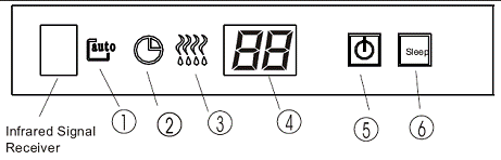
①Auto indicator
This indicator illuminates when the air conditioner is AUTO operation.
②Timer indicator
This indicator illuminates then TIMER is set ON/OFF.
③PRE-DEF. indicator (For cooling & heating mode only)
This indicator illuminates when the air conditioner starts defrosting automatically or when air control feature is activated in heating operating.
④DIGITAL DISPLAY indicator
Displays the current setting temperature when the air conditioner is in operation.
⑤OPERATION indicator
This indicator flashes after power is on and illuminates when the unit is in operation.
⑥SLEEP indicator
This indicator appears when the unit is in economic operation.
8.2 Proper symbols and their meanings
TA: Indoor ambient temperature
TE: Indoor evaporator temperature
TS: Setting temperature through the remote controller
TE1: Anti-cold wind, from Fan Off to Breeze temperature
TE2: Anti-cold wind, from Breeze to Setting Fan Speed temperature
TE3: Anti-cold wind, from Setting Fan Speed to Breeze temperature
TE4: Anti-cold wind, from Breeze to Fan Off temperature
TE5: Evaporator low temperature protection entering temperature
TE6: Evaporator low temperature protection restoring temperature
TE7: Evaporator high temperature protection, compressor off temperature
TE8: Evaporator high temperature protection, fan off temperature
TE9: Evaporator high temperature protection, restoring temperature
T3: Outdoor unit pipe sensor
T4: Outdoors temperature sensor
8.3 Systematic functions.
Remote receiving.
Testing and forced run.
Position set for indoor unit wind vane.
LED display and alarm.
On or off Timer.
Protection for the compressor.
High temperature protection of indoor heat exchanger in heating mode.
Auto defrosting and heating recovery under heating mode.
Anti cold air under heating mode.
Anti frozen under cooling mode.
8.4 Protection
8.4.1 The compressor functions protection with a delay of three minutes.
8.4.2 High temp. protection of condenser.
8.4.3 Sensor protection at open circuit and breaking disconnection
8.4.4 Temperature Fuse break protection
8.4.5 Fan Speed is out of control. When Indoor Fan Speed is too high(higher than High Fan+300RPM)or too low(lower than 400RPM), the entire unit stops and LED displays failure information and can’t returns to normal operation automatically.
8.5 Fan-only mode
Fan speed is high/mid/low/ Auto
8.6 Cooling mode
The 4-way valve is closed under cooling mode.
The action of the compressor and the outdoor fan:
Condition | Compressor | Outdoor fan | |
Temp. up | TA> Ts+1 | On | On |
TA<Ts+1 | Off | Off | |
Temp. down | TA> Ts | On | On |
TA<Ts | Off | Off |
TA: Indoor ambient temperature
TS: Setting temperature through the remote controller
Auto fan under cooling mode:
Condition T=Indoor Temp.-Setting Temp. | Indoor fan speed | |
Temp. up | T<3℃ | Low |
3℃<T<5℃ | Med. | |
T>5℃ | High | |
Temp. down | T> 3℃ | High |
1℃<T<3℃ | Med. | |
T<1℃ | Low |
Anti-freezing control to indoor evaporator under cooling mode
Condition | Compressor | Outdoor fan | ||
Temp. | Time | |||
Temp. up | T> TE6 | On | On | |
T< TE6 | >5 Minutes | Off | Off | |
Temp. down | T> TE5 | On | On | |
T< TE5 | >5 Minutes | Off | Off |
Condenser high-temperature protection under heating mode
T3 >65℃,turn off compressor.
TE5: Evaporator low temperature protection entering temperature
TE6: Evaporator low temperature protection restoring temperature
8.7 Dehumidifying mode
8.7.1 The 4-way valve is off in dehumidifying mode
8.7.2 Compressor and Indoor Fan actions in dehumidifying mode
Compressor run 5 minutes, and indoor fan run 5 minutes in low speed, then turn off the compressor, indoor fan run 5 minutes in low speed. And repeat on and off cycle.
8.7.3 Low room temperature protection:
When room temperature decreases to below 10℃, the compressor and the outdoor fan will stop(indoor fan is Breeze). Dehumidifying operation will be resumed when room temperature restores to over 13℃.
8.7.4 Under dehumidifying mode, the anti-freezing function of the indoor heat exchanger is the same as that of cooling mode.
8.8 Heating mode
8.8.1 Generally, the 4-way valve is open in heating mode, but it is closed in defrosting mode. 4-way valve must delay 2 minutes compared with compressor if the compressor changed into non-heating mode or turned off. 4-way valve doesn't delay in dehumidifying mode.
8.8.2 Generally, the outdoors fan is turned off with the on-off action of compressor in heating mode, except for the defrosting mode or the end of defrosts.
8.8.3 Action conditions of compressor under heating mode: compressor must run for 7 minutes after starting and then judge temperature. Meanwhile other protections are still valid.

|
Из за большого объема этот материал размещен на нескольких страницах:
1 2 3 |
