


Партнерка на США и Канаду по недвижимости, выплаты в крипто
- 30% recurring commission
- Выплаты в USDT
- Вывод каждую неделю
- Комиссия до 5 лет за каждого referral

Conceptual Design Report
of
Nuclotron-based Ion Collider fAcility (NICA)
(Short version)

Dubna
January 2009
Conceptual design report of Nuclotron-based Ion Collider fAcility (NICA)
(Short version)
Editors I. Meshkov, A. Sidorin
Abstract
The conception of the Nuclotron-based Ion Collider fAcility (NICA) published in Conceptual Design Report (CDR) in 2008 [1] is presented with account of the development made during the year. The conception has been proposed and developed by the NICA Group of JINR in collaboration with colleagues from different Laboratories listed below.
NICA Collaboration
Project leaders: A. Sissakian, A. Sorin
NICA group leaders: I. Meshkov, A. Kovalenko
JINR
N. Agapov, V. Alexandrov, A. Alfeev, O. Brovko, A. Butenko, E. D. Donets, E. E. Donets, A. Eliseev, I. Issinsky, G. Khodzhibagiyan, V. Karpinsky, V. Kekelidze, V. Kobets, O. Kozlov, A. Kuznetsov, V. Mikhaylov, V. Monchinsky, A. Olshevsky, Yu. Potrebennikov, A. Sidorin, G. Sidorov, V. Shevtsov, A. A. Smirnov, A. V. Smirnov, V. Toneev, G. Trubnikov, B. Vasilishin, V. Volkov, V. Zhabitsky
IHEP
O. Belyaev, Yu. Budanov, S. Ivanov, A. Maltsev, I. Zvonarev
INR RAS
V. Matveev, L. Kravchuck
Budker INP SB RAS
V. Arbuzov, Yu. Biryuchevsky, S. Krutikhin, G. Kurkin, B. Persov, V. M. Petrov, A. M. Pilan
INP and NE Bulgarian Academy of Science
A. Angelov, V. Angelov, D. Dinev, I. Geshkov, J. Stamenov
Introduction
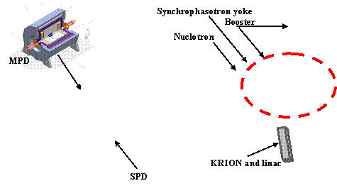
The goal of the NICA project, as formulated in the Conceptual Design Report (CDR) [1], is construction at JINR of the new accelerator facility that consists of (Fig.1)
- cryogenic heavy ion source KRION of ESIS type (see below),
- source of polarized protons and deuterons,
- the "old" linac LU-20,
- a new heavy ion linear accelerator,
- a new Booster-synchrotron (that will be placed inside of yoke of the decommissioned Synchrophasotron),
- the existing proton synchrotron Nuclotron (being developed presently to match the project specifications),
- two new superconducting storage rings of the collider,
- new set of transfer channels.
|
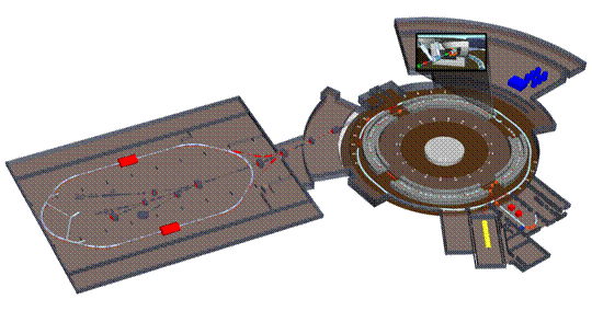

Fig.1. Scheme of the Nuclotron-based Ion Collider fAcility (NICA)
The facility will have to provide ion-ion (1¸4.5 GeV/u), ion-proton collisions and collisions of polarized proton-proton (5¸12.6 GeV) and deuteron-deuteron (2¸5.8 GeV/u) beams. Moreover, as a result of the project realization, the potential of the Nuclotron accelerator complex will be significantly increased in all the fields of its current physics program and fixed target experiments with slow extracted Nuclotron beams are presumed as well as experiments with internal target.
The collider will have two interaction points (IP). The Multi Purpose Detector (MPD), aimed for experimental studies of hot and dense strongly interacting QCD matter and search for possible manifestation of signs of the mixed phase and critical endpoint in heavy ion collisions, is located in one of them. The second one is used for the Spin Physics Detector (SPD). Concept of the MPD design is described in [2], the SPD design has been started last year.
In the Chapter 1 we describe briefly general modes of the collider operation. The Chapter 2 is dedicated to description of the facility operation in the heavy ion collision mode.
We consider here mainly the problems related to the collider omitting the technical details essential for the ion generation, the beam formation, etc. Consideration of such details can be found in the CDR [1].
Chapter 1. General modes of the collider operation
Collider will be operated at a fixed energy without acceleration of an injected beam. Correspondingly the maximum energy of the experiment is determined by the Nuclotron magnetic rigidity that is equal to about 45 T×m at the field value of about 2 T. The collider location inside existing experimental building was chosen as a baseline of the project. The building size permits to place a ring at maximum circumference of about 250 m which is equal to the Nuclotron one. In order to have the collider magnetic rigidity of 45 T×m and enough space for long straight sections the field of the bending magnets has to be increased up to about 4 T. Preliminary design of such magnets has been performed (see below) and a prototype is under development. Main problem to be solved is to form the field of required quality in a short curved magnet.
Very attractive alternative is to use "Nuclotron-type" magnets. The Nuclotron superconducting magnets are based on a cold-iron window frame type yoke and low inductance winding made of a hollow composite superconductor. The field geometry is formed by the iron yoke. The main elements of the Nuclotron, including SC magnetic system, have been fabricated by the JINR machinery workshops LHE without involving specialized industry. This work has brought a great experience to the Institute staff in the field of SC magnet design and manufacturing. Such type of magnets one plans to use for construction of SIS-100 synchrotron of the FAIR project and for the NICA Booster (see section 2.1.3 below). However, in this case the collider circumference has to be of 400–500 m that requires construction of a new building for the collider location. This possibility is under studying presently and here we describe the version of high-field magnet application only.
For luminosity preservation in ion-ion collision mode an electron and/or stochastic cooling system is planned to be used. To cover total ion energy range the electron energy of the electron cooling system has to be varied from 0.5 to 2.4 MeV. The stochastic cooling system can be operated for both polarized and proton beam cooling up to the proton energy of 12.6 GeV.
1.1. Ion-ion collisions
Main goal of the NICA facility construction is to provide collider experiment with heavy ions like Au, Pb or U in the energy range 1¸ 4.5 GeV/u at luminosity above 1∙1027 cm-2∙s-1 at the energy of 3.5 GeV/u. The conception [1] has been developed for the heaviest stable nuclei 238U92+. It was decided recently to choose the Gold nuclei 197Au79+ as the reference particles for the heavy ion collider mode. This decision was forced by significant problems of Uranium ion source creation.
To achieve the maximum design energy the Nuclotron has to accelerate fully stripped ions. To provide the ion stripping at high efficiency the ions have to be accelerated to the energy of a few hundreds of MeV/u. For this goal is used a new synchrotron ring – the Booster. To obtain necessary ion number after single turn injection the Booster has to have a sufficient circumference. This condition can be met when the Booster is located inside the Synchrophasotron yoke. The yoke provide also a required radiation shielding of the Booster.
Description of this mode of operation is presented in the Chapter 2 in more details.
1.2. Ion-proton collisions
The suggested Project allows one also to collide mass asymmetric beams including proton-ion (pA) collisions. Alongside of proper physics meaning, it is quite important as a reference point for comparison with heavy ion data. The experiment will be performed at the same MPD detector. Therefore the luminosity significantly larger than 1027 cm-2∙s-1 is not necessary. This luminosity level is achievable quite easily because of large proton number in the beam comparing with heavy ions.
The main problem that appears in this mode is the requirement of equal energy magnitudes of protons and nucleons of the colliding nuclei (nuclei energy per nucleon). This requirement leads to different magnetic rigidity of the "proton" and "ion" rings and, as a consequence, colliding of both beams at IP makes a problem for the beams steering at the chosen collider lattice. The problem can be resolved by addition of several lenses and trajectory correctors into "proton" ring near the place where the proton beam has to be deflected to the common interaction section. Such a lattice is under development presently.
In this mode the collider injection chain has to be switched fast (during a time of a few seconds) from acceleration of heavy ions to acceleration of protons. The heavy ion acceleration is provided by the same way as described in the previous section. For the proton acceleration the Booster is not necessary. The proton beam generated by duoplasmotron source is accelerated by LU-20 to the energy of 20 MeV. Single-turn injection permits to have in the Nuclotron more than 1011 protons. After adiabatic bunching the protons are accelerated at the 5-th harmonics of the revolution frequency to the experiment energy and are transferred, bunch by bunch, to the collider ring. If necessary the accelerated proton beam can be rebunched in the Nuclotron after the acceleration to form a single bunch of larger intensity.
The requirement of equality of the nucleon and proton energy (velocity!) magnitudes provides automatically condition of collision synchronization.
1.3. Polarized beam collisions
Another mode of the facility operation will be proton-proton and deuteron-deuteron polarized colliding beams in the energy range of 5 12.6 GeV for protons and 2¸5.8 GeV/u for deuterons. The luminosity above 1∙1030 cm-2∙s-1 can be achieved in the total energy range.
For the spin physics program the Booster is not used. The polarized particles are accelerated with LU-20 and, after single turn injection into the Nuclotron are accelerated to the experiment energy.
In the Nuclotron the deuteron depolarization resonances are absent in the total achievable energy range. The possibility of acceleration and extraction of polarized deuterons in the Nuclotron has been demonstrated a few years ago. The measurements of polarization degree performed by three independent groups on internal and extracted beams in November 2003 gave the value of 65 % agreed with the expected one.
For acceleration of the polarized proton beam the Nuclotron has to be equipped with insertion devices for the spin tune control to cross the depolarization resonances without loose of the polarization degree. Preliminary design of such devices was elaborated and the Nuclotron straight section length is sufficiently long to place them.
Presently the maximum achieved intensity of polarized deuterons in the Nuclotron is about 2·108 particles per cycle. The main direction of work aimed at increase of the intensity is related to the design and construction of a new high current polarized ion source with charge-exchanged plasma ionizer (IPSN) based on the equipment of CIPIOS polarized proton and deuteron source transferred to Dubna from Bloomington (Indiana University, USA). The work is carried out in collaboration with INR (Troitsk). Some parts of suitable equipment for the new source were presented by DAPHNIA (Saclay). The IPSN will provide the output beam current up to 10 mA of p and d↑ ions. d↑ ion polarization of 90% of the nominal vector mode +/-1 and tensor mode +1,-2 is expected. That will increase the accelerated polarized beam intensity at the Nuclotron up to above 1010 part/cycle.
Luminosity of the p-p collisions is limited by beam-beam effect (see section 3.2), however the required level can be reached at relatively week requirements for the bunch intensity and the bunch number in the ring (Table 1). Injection chain for the polarized ions does not include beam cooling devices. Therefore the bunch phase volume in the Table 1 is determined at the injection into the Nuclotron. Stochastic cooling application in the collider could permit to optimize the bunch parameters. However, the luminosity value of 1∙1030 cm-2∙s-1 can be reached without cooling. Therefore this luminosity level should be considered as a low estimation. The stochastic cooling is useful also to decrease the beam momentum spread that provides long polarization life-time.
Table 1. Bunch parameters for p-p collision
5 GeV | 12 GeV | |
Proton number per bunch | 6×10¹⁰ | 1.5×10¹⁰ |
Number of bunches | 10 | 10 |
Rms relative momentum spread | 10-3 | 10-3 |
Rms bunch length, m | 1.7 | 0.8 |
Rms unnormalized emittance, p×mm×mrad | 0.24 | 0.027 |
Beta-function in the IP, m | 0.5 | 0.5 |
Lasslet tune shift | 0.0074 | 0.0033 |
Beam-beam parameter | 0.005 | 0.005 |
Luminosity, cm-2s-1 | 1.1×1030 | 1×1030 |
For spin manipulation in the interaction point Siberian snakes in the collider are foreseen. One can apply the simplest version of the snake – spin rotator in form of a solenoid coaxial with particle orbit in a straight section (Fig. 2 below). Then longitudinal polarization of the particles at IP can be achieved by proper particle polarization at injection.
1.4. Alternative schemes of the collider feeding with the ions
Two schemes of the collider "feeding" with ions is under consideration now:
- in accordance with the first one during the feeding the collider RF system is switched on at the working harmonics of the revolution frequency and bunch prepared by the injection chain is injected into corresponding separatrix;
- the second scheme presumes storage in the collider of a coasting beam initially. After storage of a required ion number an adiabatic bunching and bunch compression are provided.
At the first scheme application certain requirements to the ion bunch intensity and emittance has to be met by the injection chain. To achieve the required bunch intensity a few single turn injections into the Booster is foreseen. The required bunch emittance is formed using electron cooling in the Booster. To reach the design bunch length the bunch compression is performed in the Nuclotron after acceleration. In this regime the maximum bunch number in the collider ring is limited by the injection kicker pulse duration: one needs to avoid distortion of circulating bunches during injection of a new one.
The second scheme simplifies significantly the requirements to the injection chain. The beam storage can be done using RF stacking procedure or (more preferably) with application of so called "RF barrier bucket" technique. Intensity of the injected portion defines the stacking process duration only and can be arbitrary in principle. The required beam emittance is formed during the stacking by the cooling application (electron or stochastic ones). The maximum bunch number in the collision mode is limited by requirement to avoid parasitic collisions in the vicinity of the interaction point and can be larger than at the first scheme. However at this scheme the collider has to be equipped with "Barrier Bucket RF system" and with two systems of harmonic (sinusoidal) RF. Both harmonic RF systems are turned on when storage process is over and collision regime has to be started. One of them is operated at the harmonics number coinciding with the bunch number at the collisions (it is used for the bunching of the stacked beam). Another one is operated at significantly larger harmonics number that is necessary to keep a short bunch length at reasonable RF voltage.
The second scheme is preferable for the facility operation but it requires additional space of the collider circumference for RF systems placing. Therefore, at the stage of the Conceptual Design, the first scheme is chosen as a baseline. The facility operation and injection chain parameters for this scheme are described in the Chapter 2.
1.5. Preliminary design of the Collider
The collider consists of two rings of the circumference of about 251 m (Fig. 2, Table 2) equipped with SC magnetic system that has maximum magnetic rigidity of 45 Tm. The maximum field of SC dipole magnets is about 4.0 T. The collider rings will be placed one above the other one and elements of SC magnetic system are being design as a “twin bore” magnets (Fig. 3). They have SC coils that form dipole or multipole field by application of “the cos(mq)-type” winding structure (m – the number of multipole).
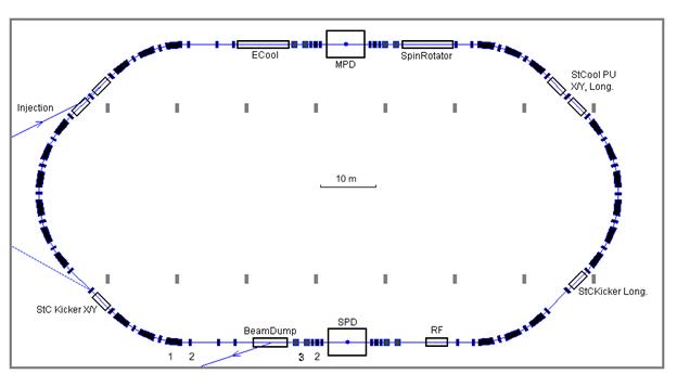
Fig. 2. NICA collider layout in the existing building. Injection and beam-dump lines are shown:
1 - dipole magnets, 2 - quadrupole magnets, 3 - separation dipoles.
Table 2. Main parameters of the collider rings
Ring circumference, m | 251.0 |
Number of interaction points (IP) | 2 |
Br max, T×m | 45.0 |
Ion kinetic energy (197Au79+), GeV/u | 1.0 ¸ 4.58 |
Dipole field (max), T | 4.2 |
Quad gradient (max), T/m | 29.0 |
Long straight sections: number / length, m | 2 / 45.0 |
Short straight sections: number / length, m | 4 / 8.8 |
Free space at IP (for detector), m | 8 |
Beam crossing angle at IP | 0 |
Table 2 (continuation)
Number of dipoles / length, m | 24 / 2.8 |
Number of vertical dipoles per ring | 2 ´ 4 |
Number of quads / length, m | 32 / 0.4 |
βx_max / βy_max in FODO period, m | 20 / 17 |
Dx_max / Dy_max in FODO period, m | 6.1 / 0.1 |
βx_min / βy_min in IP, m | 0.5 / 0.5 |
Dx / Dy in IP, m | 0.0 / 0.0 |
Betatron tunes Qx / Qy | 5.5 / 5.2 |
Chromaticity Q¢x / Q¢y | -12.4 / -12.2 |
Transition energy, g_tr | 5.0 |
Vacuum, pTorr | 100 ¸ 10 |




|
|
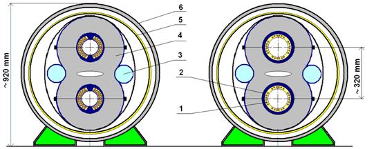

Fig. 3. "Twin bore magnets" for NICA collider rings: dipole (a) and quadrupole (b): 1 – Cos(mq) coils, 2 – "collars", 3 – He header, 4 – iron yoke, 5 – thermoshield, 6 – outer jacket
The lattice of the long straight section (Fig. 4) is designed to provide collisions at zero crossing angle.
|

|
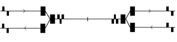
Fig. 4. Schematic view of two rings with the beam overlapping/separation in the vertical plane and the interaction region arrangement. D – dipole magnet, Q – quadrupole lens, IP – interfaction point.
Chapter 2. Facility operation for the ion-ion collision mode
2.1. Injection chain for heavy ions
2.1.1. Electron String Ion Source (ESIS) is proposed to be used for generation of heavy and multicharged ions. It is an advanced version of the Electron Beam Ion Source (EBIS). Both versions are proposed and developed originally at JINR [3]. The ESIS will have to deliver, after certain development (see below), 197Au31+ or 197Au49+ ions at intensity above 2×10⁹ ions per pulse of about 7 μs duration at repetition rate up to 50 Hz (Table 2). Minimum charge of the ions is limited by the linac parameters which are designed to accelerate the ions at Z/A ³ 0.125.
Table 3. Parameters of new ESIS "KRION-6T"
Electron energy in "the string", keV | £ 25.0 |
SC solenoid magnetic field, T | £ 6.0 |
Ions | Au25+ |
Ionization time, t, s | 0.015 |
Repetition frequency, Hz | £ 50 |
Total number of ions per pulse | 2×10⁹ |
Extraction time, ms | 6-8 |
One should mention an important characteristics of 197Au31+ and 197Au49+ ions. They both have completely filled atomic subshells: 5s24d10 for 197Au31+ and 4s23d10 for 197Au49+. Such atomic structure makes the ion more resistant to ionization/recombination processes during acceleration in the Booster and recombination with the cooling electron in electron cooler.
The source is suspended on an isolated platform at positive potential of +200 kV. That defines ion injection energy into linear accelerator – about 25 keV/u.
2.1.2. The linear accelerator consists of RFQ and RFQ Drift Tube Linac (RFQ DTL) sections. The linac accelerates the ions at A/Z £ 8 at efficiency not less than 80%. The output ion energy can be chosen in the range of (4¸6) MeV/u and will be determined by available space for the linac location. The linac is being designed and will be constructed by the group of IHEP (Protvino) [4, 5].
2.1.3. The Booster-synchrotron has maximum magnetic rigidity of 25 T∙m and the circumference of about 210 m. It allows one accelerating 197Au31+ ions up to 577 MeV/amu (Table 4).
Table 4. Basic parameters of the Booster
Ions | 197Au31+/ 197Au49+ |
Circumference, m | 210 m |
Fold symmetry | 4 |
Quadrupole periodicity | 24 |
Injection/extraction energy 197Au31+, MeV/u | 6.2/577 |
Magnetic rigidity, T·m | 2.8 ¸ 25.0 |
Max. dipole field, T | 1.8 |
Cycle duration, s | 5.0 |
Magnetic field ramp, T/s | 1.0 |
Beam Injection type | twice repeated single turn |
Beam extraction type | Single turn |
Injection store duration, sec | 0.8 |
Vacuum, Torr | 10-11 |
Max. energy, GeV/u | 6.6(p), 0.5Au31+) |
Ions per cycle | 4×10⁹ |
Magnetic system of the Booster is superconducting (SC). It is based on the experience of construction of the Nuclotron SC magnetic system and SC magnetic system of SIS-10 at FAIR project developed later [6, 7].
The Booster is equipped with electron cooling system that allows us to provide cooling of the ion beam in the energy range from injection energy up to 100 MeV/u.
After extraction from the Booster ions cross the stripping foil that is placed in the transfer line from the Booster to the Nuclotron. The stripping efficiency for Au ions at the maximum Booster energy (577 MeV/amu) is no less than 40%.
2.1.4. The Nuclotron is a SC proton synchrotron [6¸8]. It has design value of maximum magnetic rigidity of 45 T∙m (Table 5) that allows us to accelerate completely stripped ions of 197Au79+ up to the experiment energy that maximum value is of 4.6 GeV/u.
One should mention that application of two booster-synchrotrons allows us
1) to have the number of ions stored and accelerated per cycle that is sufficient for the collider luminosity achievement (see below),
2) to provide an efficient stripping of ions up to "bare" state before injection into the Nuclotron,
3) to perform nuclei acceleration in the Nuclotron up to experiment energy in the design energy range that makes possible to avoid additional acceleration in the collider and keeping collider at permanent parameters during an experiment (a significant advantage in all respects!).
Table 5. Main parameters of the Nuclotron
Parameter | Design value | Status (March 2008) |
1. Circumference, m | 251.5 | |
2. Maximum B-field, T | 2.05 | 1.5 |
3. Max. magn. rigidity, T×m | 45 | 33 |
4. Cycle duration, s | 2.0 | 5.0 |
5. B-field ramp, T/s | 2.0 | 1.0 |
6. Accelerated particles | p–U, p, d | p-Fe, d |
7. Max. energy, GeV/u | 12.6(p), 4Au79+) | 4.1(d), |
8. Intensity, ions/cycle | 1×10¹¹(p), 1×Au79+) | 1×10¹¹(p), 1×10⁶(Fe24+) 2×10⁸(d) |
The Nuclotron upgrade program (the "Nuclotron-M project") was started in 2007 and contains the following main tasks:
Modernization of the Nuclotron is one of the key points of the NICA project. We plan the completion of the first stage work by fall of 2009.
To reach the design level of the collider luminosity the bunch length before injection into collider ring has to be as short as s = 30 cm (see Table 6 below). For this reason the ion bunch in the Nuclotron, after ion acceleration on the 1st harmonics, goes through, rather standard nowadays, procedure of compression by a fast increase (“a jump”) of the RF amplitude or/and by a shift of the RF phase (see details in [1]). The RF amplitude necessary for the bunch compression procedure is of 120 kV that looks reasonable.
Total efficiency of the injection chain from the ion source to the collider is assumed to be in the range from 20 to 25%. To have the bunch intensity above 109 ions a few consequent injection pulses (2¸3) into the Booster are necessary.
2.2. The facility scheme and operation scenario
Fig. 5 demonstrates the facility scheme and parameters of the NICA corresponding to the ion-ion collision mode. The facility operation cycle (Fig. 6) provides storage of 17 bunches of the intensity of 1×10⁹ ions per bunch in each collider ring.
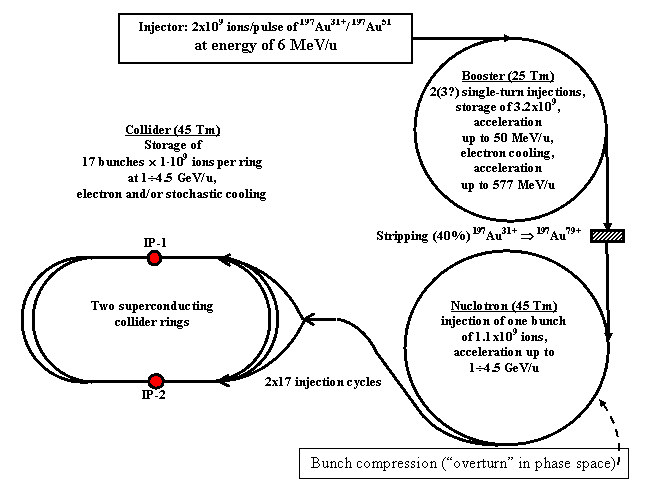

Fig. 5. Scheme and parameters of the NICA
Extraction from the Booster and the Nuclotron and injection into the Nuclotron and collider rings are performed in a single turn mode.
As the time diagram of the facility operation (Fig. 6) shows, the ion storage rate in the collider rings is defined by the Booster and Nuclotron operation cycles that are of about 4 sec, i. e. one bunch is injected into collider ring every 4 sec. Therefore filling time of both rings is about 136 sec.
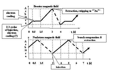

Fig. 6. Time table of the ion storage process
2.3. The collider luminosity and its limitations
For the round Gaussian beams the peak luminosity per interaction point (IP) can be calculated by the following Formula:
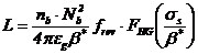 , (1.1)
where nb is the number of the bunches in the ring (equal number in both rings), Nb is the number of the ions per bunch, eg is the transverse unnormalized ("geometrical') r. m.s. emittance, b* is the beta function value in the IP, ss is the rms value of the longitudinal beam size, frev is ion revolution frequency in the ring, FHG is so called “Hour-glass effect” function defined by the following formula:
 . (1.2)
This function value is close to unit when the ss << β* and decreases with an increase of ss/β* (Fig. 7).
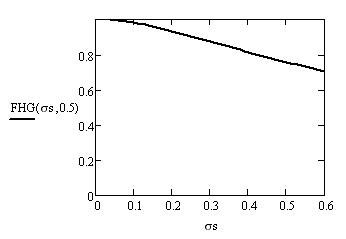
Fig. 7. Hour-glass effect function vs ss at β* = 0.5 m
To reach maximum peak luminosity one needs to meet the following obvious requirements:
- maximum bunch number in the rings,
- minimum beta function at the IP,
- maximum bunch intensity,
- minimum beam emittance,
- minimum bunch length.
The maximum bunch number is limited by the following main factors:
- "parasitic" bunch-bunch collisions outside IP that leads to an increase of the beam-beam effect;
- "electron cloud" effect;
- multibunch instability;
- technical parameters of the injection system.
Main technical limitation of the bunch number in the ring is related to an achievable pulse duration of the injection kicker tkick. To avoid distortion of circulating bunches during injection of a new one the time spacing between bunches has to be longer than about 0.5tkick. Here we assume tkick » 100 ns (which lies in well established rang of parameters) that allows us to have up to 17 bunches into each ring.
Minimum value of b* is defined mainly by allowable parameters of the focusing system. When b* is fixed the maximum value of the beta function in the ring depends on the distance from the IP to the nearest quadrupole lenses. The MPD design presumes that the minimum distance from the quadrupole lens to the IP is no less than 4 m. This limitation is sufficient even at small ion energy, when the beam emittance has to be large enough to avoid tune shift limitation. In the current conception the b* value is chosen to be 0.5 m. At the ion energy of 1 GeV/u it requires the aperture of the quadrupoles of the low beta insertion of about 80 mm. At maximum ion energy the b* can be decreased with corresponding increase of the peak luminosity.
The ion bunch intensity can be limited by the following effects:
- Laslett tune shift,
- Beam-beam effect,
- Coherent instabilities.
The proposed NICA injection chain is designed to provide in the collider rings of the bunch intensity of 109 ions and has a technical reserve required for future development of the facility. At the Au79+ bunch intensity of 109 ions the rms bunch length corresponding to the threshold peak current of the longitudinal instability lies between 20 and 30 cm. At the same conditions the bunch intensity is below than the threshold of transverse instability [1]. The requirements to the vacuum chamber impedance and stability of the longitudinal motion at the electron cooling are the issues addressed to the collider technical design stage. Finally the bunch length is chosen as a compromise between two contradicting requirements. On the one hand the bunch length has to be as small as possible to avoid a "hour glass" effect (Formula 1.2 and Fig. 7)) and to provide the luminosity concentration in the central part of the detector (Inner Tracker or Silicon Strip Detector [2]). On the other hand a small bunch length leads to increase of the bunch peak current that can provoke coherent instability and requires high RF voltage for matching of the bunch with the RF. The last limitation is economical one – the required RF voltage amplitude determines the cost of the RF system. For reduction of the RF voltage amplitude to reasonable level (of 100–200 kV) the RF system will be operated at high harmonics of the revolution frequency. In the current design the harmonics number is chosen to be 102.
Table 6 presents the chosen ion beam parameters and luminosity magnitudes at 3 values of ion energy. The factors of beam space charge, which characterize the luminosity limitations, are presented in there as well. They are so called "Lasslet (or incoherent) tune shift" and "the beam-beam effect".
The first one, Lasslet tune shift, can be estimated for a round Gaussian bunch as
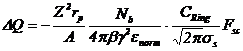 . (1.3)
Here Ze and A are the ion charge and atomic weight, rp is proton classic radius, β and g are relativistic parameters of the ion, enorm is the ion bunch normalized emittance, CRing is the collider ring circumference, Fsc is the space charge image force correction factor (usually Fsc ~ 1).
The second effect is described by “the beam-beam parameter” (for one IP!)
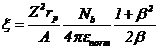 . (1.4)
Both values (1.3) and (1.4) do not depend on the bunch number in the ring and should not exceed certain levels to have stable beams. For our estimates we have chosen
DQ < 0.05, x < 0.0
Then both values limit the ratio Nb/enorm and one can express luminosity via DQ (FSC =1) and x :
 . (1.6)
 . (1.7)
Here c is the speed of light.
In the NICA energy range the limiting effect is the Lasslett tune shift (Table 6).
Table 6. Collider beam parameters and luminosity for Au-Au collisions
Ion number per bunch | 1∙109 | ||
Number of bunches | 17 | ||
Beta-function at the interaction point, m | 0.5 | ||
Rms bunch length, m | 0.3 | ||
Incoherent tune shift | 0.05 | ||
Ion energy, GeV/u | 1.0 | 3.5 | 4.5 |
Rms momentum spread | 0.001 | ||
Luminosity per one interaction point, 1027 cm-2s-1 | 0.06 | 1.05 | 1.9 |
Rms beam emittance (geometrical), p×mm×mrad | 3.9 | 0.256 | 0.14 |
Without a beam cooling, during the experiment the beam emittance and the bunch length increase due to IBS process. The expected IBS growth time values in the collider are of the order of 10-50 s at the 3.5 GeV/u ion energy. In the required energy range the both electron and stochastic cooling method can be used. However there is a lack of the world experience presently of the cooling systems of required parameters. To cool down the heavy ions the maximum electron energy has to be about 2.4 MeV. The highest energy of the electron beam reached in the Recycler cooling system (FNAL) is equal to about 4.3 MeV (that corresponds to the ion energy of about 8 GeV/u). Unfortunately this system is operated at low magnetic field value that does not allow to achieve short cooling time. The other existing systems with magnetized electron beams are operated at the electron energy below 300 keV. Concerning stochastic cooling there is no experience of the bunched ion beam cooling. Stochastic cooling of bunched beam has been demonstrated two years ago in pioneering work at RHIC with Gold ion beam of a high energy and for longitudinal degree of freedom only. Due to some peculiarities of that cooling system its design can not be applied directly for bunched beam cooling at low ion energy. And no experience exists yet for stochastic cooling of transverse degrees of freedom of bunched beam. Therefore design and construction of the cooling system (independently – electron or stochastic) require R&D stage of the work.
Conclusions
The luminosity of the order of 1027 cm-2s-1 in heavy ion collisions will be reached owing to the following peculiarities of the NICA design.
1. Collider operation with low beta function at the interaction point. The short (of about 10 m) interaction region allows us to have maximum beta functions in the triplets of about 90 m when the beta functions in the collision point are of 0.5 m. At such conditions the maximum beam radius in the lenses of the low beta insertion section is about 4 cm (at 1 GeV/u) that requires reasonable aperture of the lenses.
2. Short bunch length. The rms bunch length of about 30 cm makes possible to reduce significantly "the hour glass effect" and to obtain required luminosity distribution along the interaction region. The length of the inner tracker of the MPD is chosen to be of 40 cm that allows to accept by the tracker, at the given bunch length, of about 75% of the luminosity.
3. Collider operation at the beam emittance corresponding to the space charge limit. In the NICA energy range the luminosity is limited by the incoherent tune shift value. If the ion number per bunch and the tune shift DQ are fixed the luminosity is scaled with the energy as b3g3. The formation and preservation of low emittance value corresponding to the tune shift limit is produced by electron and/or stochastic cooling application at the experiment energy.
4. High collision repetition rate. The collider is operated at the bunch number of 10¸20 in each ring. This is achieved at well established injection kicker parameters (the kicker pulse duration is about 100 ns) by means of injection into the collider of bunches of a short length. The bunch of the required length is formed in the Nuclotron after the acceleration. Small longitudinal emittance value required for the bunch compression in the Nuclotron is provided by the electron cooling of the ion beam in the Booster.
5. Long luminosity life-time. For the luminosity preservation the beam cooling is foreseen. In equilibrium between intrabeam scattering (IBS) and the cooling the luminosity life-time is limited mainly by the ion interaction with the residual gas atoms. The vacuum conditions in the collider rings will provide the beam life time of a few hours. The beam preparation time is designed to be between 2 and 3 minutes. Therefore, the mean luminosity value is closed to the peak one.
Numerical simulations of the beam dynamics in the collider under stochastic and electron cooling are in progress. The electron cooling system of the collider will be designed and constructed in collaboration with BINP (Novosibirsks), FZJ (Juelich, Germany) and VEI (All-Russian Electrotechnical Institute, Moscow). Elaboration of the stochastic cooling system will be performed in collaboration with CERN, GSI, FZJ, FNAL and BNL. During R&D stage one plans to test a prototype of the stochastic cooling system at the Nuclotron on a magnetic field plateau.
References
1. Design and Construction of Nuclotron-based Ion Collider fAcility (NICA), Conceptual Design Report, edited by I. Meshkov and A. Sidorin, JINR, Dubna, 2008 (see http://nucloserv. *****/nica_webpage/Nica_files/reports/CDR_07/CDR_NICA%20.html).
2. V. D. Kekelidze, A. N. Sisakian, A. S. Sorin et al., The MultiPurpose Detector – MPD, Letter of intent, Dubna, 2008.
3. E. D. Donets, in "Physics and Technology of Ion Sources", I. G. Brown, Wiley &Sons, NY, 1989, p. 245; E. D. Donets, et al., Rev. Sci. Instrum., .
4. V. A. Teplyakov, The First CW Acclerator in USSR and A Birth of Accelerating Field Focusing, Proceedings of EPAC 2006, Edinburgh, Scotland THPPA03, Prize Presentation;
5. O. K. Belyaev, Yu. Budanov, A. Maltsev, I. Zvonarev, NICA RFQ Technical design report, Protvino, 2008.
6. Khodzhibagiyan, H. G., and Smirnov, A. A., The concept of a superconducting magnet system for the Nuclotron, Proc. of the 12th Int. Cryogen. Eng. Conf., 1988, pp. 841-844.
7. Baldin, A. M., et al., Superconducting fast cycling magnets of the Nuclotron, IEEE Trans. on Applied Superconductivity, vol. 5, 2 (1995) p. 875-877.
8. A. D. Kovalenko, Nuclotron: status & future, Proceedings of EPAC 2000, Vienna, Austria.
