
Партнерка на США и Канаду по недвижимости, выплаты в крипто
- 30% recurring commission
- Выплаты в USDT
- Вывод каждую неделю
- Комиссия до 5 лет за каждого referral
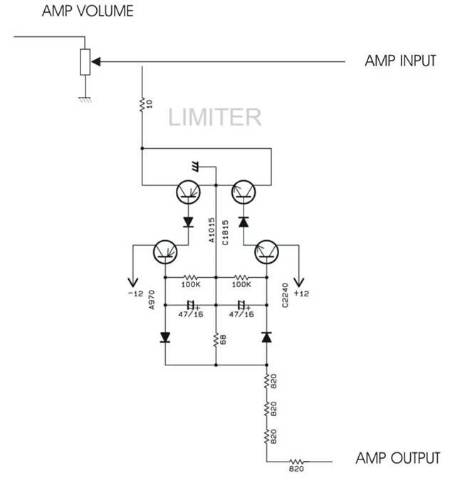
УМЗЧ с лимиттером
http://*****/unch-i-zvukotekhnika/usilitel-moshhnosti-500-vatt. html
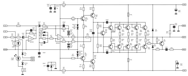
Вот схема усилителя мощности:
Добавлено: представленный усилитель Apex B500 (а точнее два рабочих экземпляра) может работать в мостовом режиме. Для этого предусмотрены отдельные входы, обозначенные на схеме A и B. Схема подключения и принцип описаны ниже в 6-ом комментарии. При мостовом включении усилители мощности могут выдать 700…800 ватт на нагрузку 8 Ом.
Выводы A и B используются для мостового режима включения двух усилителей мощности. Сигнал с вывода A первого усилителя мощности, усиленный первым операционным усилителем, идет на контакт B второго УМ и сразу поступает на второй каскад ОУ. Для стандартного подключения их можно не использовать. Мостовое включение можно применить, например, для сабвуферного канала. При этом выходная мощность должна составить около 800 Вт на 8 Ом.
Если произойдет пробой транзистора(ов), и на выходе будет постоянная составляющая, то защитный блок отключит цепь питания. Его можно заменить вот такой защитной схемой:
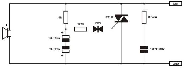
При появлении на выходе напряжения +/-35 вольт, симистор замыкает выход на общий провод, и сгорают предохранители, установленные в каждом плече усилителя мощности (см. схему).
Подытожим сказанное. Для непрофессионального (домашнего) использования усилителя мощности контакты “А”, “В”, “PRO” особого интереса не представляют. Что касается последнего, то при качественном охлаждении цепь электронного драйвера не нужна.
Если нет ОУ NE5532, то его можно заменить, например, на TL072 или другой сдвоенный операционный усилитель.
Вместо MJE15033/MJE15032 можно установить 2SC4793/2SA1837.
Фоторезистор NSL32 можно заменить на 3ОР124А или просто установить светодиод в качестве индикатора или всю ограничивающую цепь заменить на такую:
Лимиттер штука нужная для таких усилителей если акустика слабее усилителя. Ну и для того чтобы не выходить за пределы приемлимого звучания но данная схема увы .Лимитирование нужно чтобы не клиповал усилитель а это зависит от питания (до начала ограничения синусоиды) и выходного уровня. Грубо привязка выходного уровня и напряжение питания. Вот более лучшее решение (пост 53)
http://forum. *****/index. php? s=d17151d8110fb10751&showtopic=7273&st=42&start=42

DA 1.1 Это симметричный вход. Вариант включения на DA 1.2 считают лучшим чем сопротивление оптопары в цепи ОС
http:///Solid/DIY-Lightspeed-Passive-Attenuator/
Lightspeed Passive Attenuator
The Lightspeed Passive Attenuator designed by George Stantscheff (GeorgeHiFi on the audio forums) is by far the very best passive attenuator that I have heard. There is perfect clarity, a widened soundstage, separation of instruments, and seemingly infinite detail. What makes this passive preamplifier interesting is that there are no contact points in the form of a "wiper" as in the case of a potentiometer or "switches" as may be with a discrete stepped attenuator. The key components in the Lightspeed Attenuator are Silonex NSL-32SR2 Optocouplers (PDF - 34kB). The optocoupler device is a sealed unit which consists of a high performance LED that shines on a light dependent resistor (LDR).
Figure 1: Optocoupler (LED and Light Dependent Resistor)
The operating principle of the optocoupler is fairly simple. As the intensity of the LED varies, so does the internal resistance of the LDR (resistance decreases with increasing light). So in the case of the Lightspeed Attenuator, we change the volume (resistance) by changing the intensity of the using a series and shunt combination of optocouplers the attenuator can be configured to produces a constant input and output impedance, regardless of where the voltage control setting is.
It is worth mentioning that the Lightspeed Passive Attenuator is not for every audio system though. First off, it is a passive attenuator so there is no gain. Also, your source output impedance needs to be less than about 100 ohms which makes it suitable for use with several sources. The Lightspeed Attenuator works best with amplifiers that have input impedance greater than about 50k. If you would like to use the attenuator with a low input impedance amplifier best results are achieved by using a suitable buffer between the attenuator and amplifier.
DIY "Lightspeed Attenuator" - Passive LDR Volume Control
The schematic for the Lightspeed Passive Attenuator is shown below. George has chosen to share his Lightspeed Attenuator with the DIY community provided that it is only used for personal use only. Details about George's commercial offering of the Lightspeed Passive Attenuator are provided at the bottom of this page.
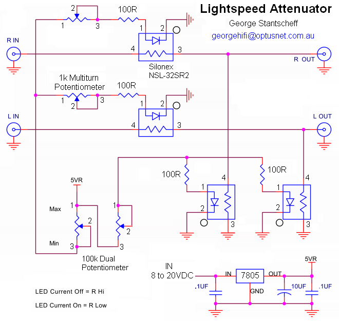
Figure 2: Lightspeed Passive Attenuator Schematic
The following will required to build a Lightspeed Attenuator.
· 5 VDC power supply.
· 100k dual log or linear potentiometer (quality does not matter as this only controls voltage and not the audio signal)
· Four 100 Ohm 1/4W resistors
· Two 1k to 5k multi-turn potentiometers
· Two matched pairs of Silonex NSL-32SR2 Light Dependent Resistors (LDR)
· Wire
· Four RCA Jacks
· A suitable enclosure
· Miscellaneous Hardware: knobs, feet, switches...
There are four leads from each optocoupler. The two shorter leads are for the LED portion. A white dot on the optocoupler capsule near the short leads marks the cathode of the LED (ie. V- or GND). The two longer leads on the opposite end of the optocoupler device are the LDR (there is no negative or positive).
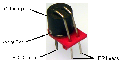
Figure 3: Optocoupler Device Identification
If we take two of these resistor legs from separate optocouplers and tie them together we have formed the equivalent of a potentiometer. The top resistor has one free leg and one twisted leg. The free leg takes the signal from one channel of your source. The LDR leads that are tied together form the output go to the signal input of your amplifier. The last leg is connected to the signal ground. If we vary the value of the resistor going to ground then we vary the overall output impedance of the potentiometer. Your amp will like to see a steady output impedance. The value of the series resistor plus the value of the shunt resistor equals the output impedance of Lightspeed Attenuator. So as the series resistor increases or decreases in value we want the shunt resistor to do exactly the opposite.
For each channel, we need to vary the intensity of the LED inversely with each other. Using a 5VDC source and a 100k potentiometer (pot) we vary the intensity of the LEDs. A dual pot has 6 legs on it. 3 for each section. If you connect pins 1 and 2 together on the first section of the pot and connect pins 2 and 3 together in the same way on the second section we have just created two variable resistors that change in resistance opposite of each connecting pin 3 of section 1 to pin 1 of section 2 and connecting that to the +5VDC from your power supply we can adjust intensity of the LEDs. The 100 ohm resistor is used to limit the current to the LEDs.
The 1k to 5k multi-turn pot allows us to make up for the matching differences between the optocoupler pairs. What's this? The Silonex Optocouplers resistance does not vary consistently from device to device. Consistency is very poor. In general, you will need to buy multiple optocouplers (25 or more) and measure their resistance at several different current plotting the results you can match optocouplers that 'track' in a similar fashion. When you find two that match, set them aside and begin to find another two that match each other. It is not necessary that all 4 match each other but the series resistors must match and the shunt resistors must match.
