
Партнерка на США и Канаду по недвижимости, выплаты в крипто
- 30% recurring commission
- Выплаты в USDT
- Вывод каждую неделю
- Комиссия до 5 лет за каждого referral
3.2.6.3 The following items, and others not specifically permitted by these rules, are prohibited: | 3.2.6.3 Следующие пункты, и другие, не определенно разрешенные по этим правилам, запрещены: |
(a) Mainsheet cleats, mainsheet horse, track or traveller. | (a) Клеммы Mainsheet, mainsheet лошадь, отслеживают или путешественник. |
(b) Suction bailers and bilge pumps. | (b) Ковши всасывания и трюмные помпы. |
(c) Decking or spray covers of any sort. | (c) Отделка или покрытия брызгов любого вида. |
(d) Any apparatus or contrivance outboard, or extending outboard, which is, or may be used to assist In supporting the helmsman outboard. | (d) Любой аппарат или катер приспособления, или простирающийся катер, который является, или может использоваться, чтобы помочь В поддержке рулевого катера. |
(e) Any fittings constructed in part or whole of titanium.(FROM 1 MARCH 2006) | (e) Любые приспособления, построенные частично или весь титан. (ОТ 1 МАРТА 2006) |
3.2.7 Buoyancy | 3.2.7 Плавучесть |
3.2.7.1 The hull shall be fitted with three buoyancy units in the form of inflated air bags made of strong fibre-reinforced material. | 3.2.7.1 Корпус будет оснащен тремя единицами плавучести в форме надутых воздушных подушек, сделанных из сильного укрепленного волокном материала. |
Each unit shall be 45 +/- 5 litres. | Каждая единица должна быть 45 +/-5 литров. |
Each unit shall be equipped with a fill valve that positively prevents the accidental release of air (i. e.- Non-return valves and threaded valves with screw-on caps). | Каждая единица должна быть оборудована заполняющимся клапаном, который положительно предотвращает случайный выпуск воздуха (то есть - клапаны Невозвращения, и пронизывал клапаны с винтом - на заглавных буквах). |
The minimum weight of each unit shall be 200 grams. | Минимальный вес каждой единицы должен быть 200 граммов. |
3.2.7.2 One unit shall be placed along the whole width of the aft transom and one unit shall be placed along each side between the midship frame and the mast thwart bulkhead. | 3.2.7.2 Одна единица должна быть помещена по целой ширине в кормовой части, транец и одна единица должны быть помещены по каждой стороне между структурой среднего сечения, и мачта мешают переборке. |
3.2.7.3 Buoyancy units shall be securely fastened to the hull by three straps for each unit, each strap shall be 45 mm +/- 6mm wide. 1 backing plate in GRP boats of metal 50 +/- 10 mm x 20 +/- 5 mm x 2 +/- 1 mm and 1 fixing plate, 50 +/- 10 mm x 20 +/- 5 mm x 2 +/- 1 mm if metal or 50 +/- 10 mm x 20 +/- 5 mm x 9 +/- 1 mm if plastic, shall be used for fastening of each strap. At the aft transom centre strap a bigger plate 50 +/- 10 mm x 50 +/- 10 mm x 2 +/-1 mm if metal or 50 +/- 10 mm x 50 +/- 10 mm x 9 +/-1 mm if plastic for combined use with the toe-strap shall be used. | 3.2.7.3 Единицы плавучести должны быть надежно закреплены на корпус тремя ремнями для каждой единицы, каждый ремень должен быть 45 мм +/-6mm широкий. 1 пластина поддержки в лодках GRP металлических 50 +/-10 мм x 20 +/-5 мм x 2 +/-1 мм и 1 пластина установки, 50 +/-10 мм x 20 +/-5 мм x 2 +/-1 мм, если металл или 50 +/-10 мм x 20 +/-5 мм x 9 +/-1 мм, если пластмасса, должна использоваться для того, чтобы закрепить из каждого ремня. В в кормовой части ремень центра транца большая пластина 50 +/-10 мм x 50 +/-10 мм x 2 +/-1 мм, если металл или 50 +/-10 мм x 50 +/-10 мм x 9 +/-1 мм, если пластмасса для объединенного использования с ремнем пальца ноги должна использоваться. |
3.2.7.4 The owner is responsible at all times for the buoyancy and for ensuring that at intervals of not more than12 months the buoyancy is tested and the measurement certificate endorsed by a measurer or a responsible club officer. | 3.2.7.4 Владелец ответственен всегда за плавучесть и за то, чтобы гарантировать, что с промежутками в не больше than12 месяцы плавучесть проверена и свидетельство измерения, подтвержденное мерителем или ответственным чиновником клуба. |
The measurement certificate shall not be valid until so endorsed. | Свидетельство измерения не будет действительно пока столь не подтверждено. |
3.2.7.5 The measurer shall witness a buoyancy test as follows: | 3.2.7.5 Меритель должен засвидетельствовать тест плавучести следующим образом: |
The boat shall be swamped with water and with iron weights of not less than 60kg placed aft of and within 100mm of the midship frame, it shall float with the gunwales clear of the water. | Лодка должна затопиться с водой и с железными весами не меньше чем 60 кг, помещенных в кормовой части и в пределах 100mm структуры среднего сечения, это должно плавать с планширами, свободными от воды. |
The measurer shall make sure that the buoyancy and its fastening are sound, and that inflatable buoyancy shows no visible signs of deflation, deterioration or damage. | Меритель должен удостовериться, что плавучесть и ее закрепление являются звуковыми, и что надувная плавучесть не показывает никаких видимых признаков дефляции, ухудшения или повреждения. |
3.2.7.6 The first buoyancy test shall normally be completed at the time of the first measurement of the boat. | 3.2.7.6 Первый тест плавучести должен обычно заканчиваться во время первого измерения лодки. |
However, if the measurer certifies that the buoyancy test could not be taken at that time, but in all other respects the class rules are satisfied the measurement certificate may be issued but with the endorsement “Not valid until a buoyancy test has been passed.” | Однако, если меритель удостоверяет, что тест плавучести не мог быть взят тогда, но во всех других отношениях правила класса удовлетворены, что свидетельство измерения может быть выпущено, но с одобрением “Не действительный, пока тест плавучести не передали.” |
3.2.8 Weight | 3.2.8 Вес |
3.2.8.1 The weight of the hull in dry condition, including: rudder gudgeons fixed to the aft transom, buoyancy straps, toe straps and associated fixings (without removable foam or protection), mast step, block fittings permanently attached, but excluding: corrector weights, blocks, mainsheet, buoyancy air bags, painter, bailer, paddle, compass (with bracket if any) and fixings, retaining clips for water bottles, food containers or other personal equipment and fixings, and all other not specifically permitted items, shall not be less than 32 kg. | 3.2.8.1 Вес корпуса в сухом условии, включая: пескари руля установили к в кормовой части транец, ремни плавучести, ремни пальца ноги и связанные установки (без сменной пены или защиты), шага мачты, приспособления блока постоянно были свойствены, но исключая: веса корректора, блоки, mainsheet, воздушные подушки плавучести, живописец, ковш, весло, компас (со скобкой, если любой) и установки, сохраняя скрепки для водных бутылок, контейнеров пищи или другого личного оборудования и установок, и всех другой не определенно разрешенный пункты, не должны быть меньше чем 32 кг. |
3.2.8.2 If the weight of the hull in the same condition as prescribed in CR 3.2.8.1 but including buoyancy air bags is less than 35 kg but not less than 32.6 kg wood corrector weights shall be fitted to bring the hull weight up to not less than 35 kg. | 3.2.8.2 Если вес корпуса в том же самом условии как предписано в CR 3.2.8.1, но включая воздушные подушки плавучести является меньше чем 35-килограммовым, но не меньше чем 32.6-килограммовые деревянные веса корректора должны быть приспособлены, чтобы принести весу корпуса до не меньше чем 35 кг. |
The corrector weights shall be permanently fitted, half to the forward transom and half to the aft transom. | Веса корректора должны постоянно приспосабливаться, половина к передовому транцу и половине к в кормовой части транец. |
No corrector weights shall be removed or altered without the boat being re-weighed by an official measurer. | Никакие веса корректора не должны быть удалены или изменены без лодки, повторно взвешиваемой официальным мерителем. |
The weight of each corrector shall be stamped or otherwise marked on the corrector and endorsed on the measurement certificate. | Вес каждого корректора должен быть отпечатан или иначе отмечен на корректоре и подтвержден на свидетельстве измерения. |
(See also CR 3.2.7.1 for minimum weight of buoyancy air bags.) | (См. также CR 3.2.7.1 для минимального веса воздушных подушек плавучести.) |
3.3 Daggerboard | 3.3 Шверт |
3.3.1 Materials | 3.3.1 Материалы |
3.3.1.1 The daggerboard shall be made of either wood or EPOXY as specified below | 3.3.1.1 Шверт должен быть сделан или леса или ЭПОКСИДНОЙ СМОЛЫ как определено ниже |
Wood: | Лес: | ||
Plywood | A single sheet of commercially available plywood with five plies shall be used. Manufactures shall, upon request, supply a supply and specification sheet of plywood used. | Фанера | Единственный лист коммерчески доступной фанеры с пятью плие должен использоваться. Изготовление, после запроса, будет поставлять поставку и лист спецификации используемой фанеры. |
Glue | Epoxy, for bonding battens to the daggerboard only. | Клей | Эпоксидная смола, для того, чтобы связывать доски к шверту только. |
Paint | Clear vamish or clear epoxy, suitable for marine use. | Краска | Очистите vamish или ясную эпоксидную смолу, подходящую для морского использования. |
wood | Any type, for battens only. | лес | Любой тип, для досок только. |
EPOXY: | ЭПОКСИДНАЯ СМОЛА: | ||
Resin | Epoxy resin for EPOXY lamination (shall not be coloured) | Смола | Смола эпоксидной смолы для расслоения ЭПОКСИДНОЙ СМОЛЫ (не будет окрашен), |
Fcam Core | Durable, non-absorbent closed cell PVC foam. 1.3mm (+\- 10%) 60 kg\m3 (+/- 10%) | Ядро Fcam | Длительная, негигроскопическая закрытая пена поливинилхлорида ячейки. 1.3mm (+ \-10 %) 60 kg\m3 (+/-10 %) |
Unidirectional 600 | Unidirectional mat of E glass fibres, 600 gr\m2 (+\- 10%) | Однонаправленные 600 | Однонаправленный мат стекловолокон E, 600 gr\m2 (+ \-10 %) |
Woven cloth 280 | Cloth of woven or otherwise biaxial applied skeins of continuous E glass fibres 280 gr\m2 (+\- 10%) (Pre-impregnated cloth is not permitted) | Ткавшая ткань 280 | Ткань ткавшего или иначе двуосные прикладные мотки пряжи непрерывных стекловолокон E 280 gr\m2 (+ \-10 %) (Предпропитанная ткань не разрешается), |
Mat 100 | Chopped strand mat of E glass, 100 gr\m2 (+\- 10%) (shall not be coloured) | Мат 100 | Расколотый мат берега стакана E, 100 gr\m2 (+ \-10 %) (не будет окрашен), |
Glue | Epoxy, for bonding battens to the daggerboard Only. | Клей | Эпоксидная смола, для того, чтобы связывать доски к шверту Только. |
Gelcoat | Shall be clear. | Гелькаут | Будет ясным. |
wood | лес | Любой тип, для досок только. |
Manufacturers shall, upon request, supply a laminated sample and specifications of all materials used. | Изготовители, после запроса, будет поставлять слоистый образец и спецификации всех используемых материалов. |
3.3.1.2 Non metallic reinforcement (bushing) of diameter not more than 20 mm may be used around holes, screws, rivets or bolts. | 3.3.1.2 Не металлическое укрепление (втулка) диаметра не больше чем 20 мм могут использоваться вокруг отверстий, винтов, заклепок или болтов. |
3.3.1.3 Laminate specification for EPOXY daggerboard: | 3.3.1.3 Расщепить спецификацию для шверта ЭПОКСИДНОЙ СМОЛЫ: |
Mould side Gelcoat | Сторона слоя гелькаута |
100 mat | 100 мат |
280 woven doth to be applied with one set of fibres running parallel to the aft edge of the daggerboard | 280 ткавший делает, чтобы быть примененным с одним набором волокон, идущих параллельно в кормовой части край шверта |
280 woven doth to be applied with one set of fibres running parallel to the aft edge of the daggerboard | 280 ткавший делает, чтобы быть примененным с одним набором волокон, идущих параллельно в кормовой части край шверта |
600 unidirectional to be with the fibres to the aft edge of the daggerboard | 600 однонаправленный быть с волокнами к в кормовой части краем шверта |
Foam core 13\60 | Пена удаляет сердцевину 13\60 |
600 unidirectional to be with the fibres to the aft edge of the daggerboard | 600 однонаправленный быть с волокнами к в кормовой части краем шверта |
280 woven doth to be applied with one set of fibres running parallel to the aft edge of the daggerboard | 280 ткавший делает, чтобы быть примененным с одним набором волокон, идущих параллельно в кормовой части край шверта |
280 woven doth to be applied with one set of fibres running parallel to the aft edge of the daggerboard | 280 ткавший делает, чтобы быть примененным с одним набором волокон, идущих параллельно в кормовой части край шверта |
100 mat | 100 мат |
Mould side gelcoat | Сторона слоя гелькаута |
3.3.1.4 For EPOXY foils the manufacturer’s name, a manufacturer generated mould identification number as well as the year of manufacture shall be laminated into the daggerboard in characters 10 (+/-2) mm high on the starboard side, 25 (+5/-0) mm below the bottom edge of the stop batten. | 3.3.1.4 Поскольку ЭПОКСИДНАЯ СМОЛА мешает названию изготовителя, изготовитель произвел идентификационный номер почвы, так же как год изготовления будет слоистым в шверт в характерах 10 (+/-2) мм высоко на стороне правого борта, 25 (+5/-0) мм ниже базового края доски остановки. |
For wooden foils, the manufacturer’s name and the month and year of manufacture shall be indelibly marked in the same position and with characters of the same size. | Для деревянной фольги, название изготовителя и месяц и год изготовления должны быть несмываемо отмечены в том же самом положении и с характерами того же самого размера. |
3.3.2 Shape | 3.3.2 Форма |
3.3.2.1 The daggerboard shall be generally a rectangular flat plane in shape except that the lower corners shall be rounded to a radius of no more than 32mm, and the upper corners shall be rounded to a radius of no more than 5 mm. | 3.3.2.1 Шверт должен быть вообще прямоугольным плоским самолетом в форме за исключением того, что более низкие углы должны быть округлены к радиусу не больше, чем 32mm, и верхние углы должны быть округлены к радиусу не больше, чем 5 мм. |
Upper corners and stop batten edges shall have no sharp projections. | Верхние углы и края доски остановки не должны иметь никаких острых проектирований. |
3.3.2.2 The thickness of the daggerboard (excluding bevels) shall be not less than 14mm (12mm for wooden construction) and not more than 15mm. | 3.3.2.2 Толщина шверта (исключая скашивает) должна быть не меньше чем 14mm (12mm для деревянного строительства) и не больше чем 15mm. |
Bevelling is permitted between all edges (except for the top edge) and the bevelling limits, situated 60mm from all edges. | Скашивание разрешается между всеми краями (за исключением главного края) и пределов скашивания, расположенных 60mm от всех краев. |
There shall be no bevelling underneath the stop battens. | Не будет должно никакого скашивания под досками остановки. |
3.3.2.3 The overall length of the daggerboard shall be 1067 +/- 5 mm and the width 285 +/- 5mm. Within these limits, the length and width shall each not vary by more than 3mm. | 3.3.2.3 Полная длина шверта должна быть 1067 +/-5 мм и ширина 285 +/-5mm. В пределах этих пределов, длина и ширина не должны каждый изменяться больше чем 3mm. |
3.3.2.4 The daggerboard shall be fitted with stop battens, one on each side of the daggerboard. | 3.3.2.4 Шверт будет оснащен досками остановки, один на каждой стороне шверта. |
Sizes and shapes of stop battens shall be generally uniform without cut-outs and/or sudden changes. | Размеры и формы досок остановки будут вообще однородны без очертаний и/или внезапных изменений. |
The battens shall be made from wood and extend over the full width of the board with the top of the battens level with the top of the board. | Доски должны быть сделаны от леса и должны простираться по полной ширине правления с вершиной уровня досок с вершиной правления. |
The depth shall be 35 +/- 5mm throughout. | Глубина должна быть 35 +/-5mm повсюду. |
The thickness of the assembled stop battens and daggerboard shall be 45 +/-5mm throughout. | Толщина собранных досок остановки и шверта должна быть 45 +/-5mm повсюду. |
The exposed edges of the battens shall be rounded to a radius of 5 +0/-2 mm. | Выставленные края досок должны быть округлены к радиусу 5 +0/-2 мм. |
The battens shall be fixed with glue, and two 5 (+/-1.5) mm metal bolts and nuts. | Доски должны быть установлены с клеем, и два 5 (+/-1.5) болты металла мм и орехи. |
The battens shall be fixed with glue, and two 5 (+/-1.5) mm metal bolts and nuts. | Доски должны быть установлены с клеем, и два 5 (+/-1.5) болты металла мм и орехи. |
3.3.3 The weight of the daggerboard, without attachment or positioning features, shall be not less than 2.0kg. | 3.3.3 Вес шверта, без приложения или помещающих особенностей, должен быть не меньше чем 2.0kg. |
Ballasting or cut-outs of the daggerboard are prohibited. | Материал для балластировки или очертания шверта запрещены. |
The centre of gravity of the assembled daggerboard and stop battens shall not be less than 520mm away from the lower edge. | Центр тяжести собранного шверта и досок остановки не должен быть меньше чем 520mm далеко от более низкого края. |
3.3.4 The daggerboard shall float, and shall be attached to the boat. | 3.3.4 Шверт должен плавать, и должен быть присоединен к лодке. |
One hole may be drilled through the daggerboard and the battens in any place. | Одно отверстие можно сверлить через шверт и доски в любом месте. |
Its diameter shall not exceed 10mm. | Его диаметр не должен превышать 10mm. |
An elastic cord or lanyard may be used to attach the daggerboard to the hull. | Упругий шнур или вытяжной шнур могут использоваться, чтобы приложить шверт к корпусу. |
A small shackle may be used to attach the cord or lanyard, either to the hull or to the daggerboard. | Маленькие кандалы могут использоваться, чтобы приложить шнур или вытяжной шнур, или на корпус или на шверт. |
3.3.5 The daggerboard may be held in the daggerboard case by a loop of (elastic) cord. | 3.3.5 Шверт может быть проведен в случае шверта петлей (упругого) шнура. |
The cord may be fixed to the daggerboard case through two eyes or to the mast thwart bulkhead through two holes, with a diameter of not more than 10mm. | Шнур может быть установлен к случаю шверта через два глаза, или к мачте мешают переборке через два отверстия, с диаметром не больше чем 10mm. |
The position of the eyes or holes is optional. | Положение глаз или отверстий является дополнительным. |
3.3.6 Daggerboards presented for first measurement between 1 March 2004 and 28 February 2005 may conform to either the above rules, or the rules valid before 1 March 2004. | 3.3.6 Шверты, представленные для первого измерения между 1 марта 2004 и 28 февраля 2005 могут соответствовать или вышеупомянутым правилам, или правилам, действительным до 1 марта 2004. |
Daggerboards presented for first measurement from 1 March 2005 shall conform to the above rules. | Шверты, представленные для первого измерения с 1 марта 2005 должны соответствовать вышеупомянутым правилам. |
Daggerboards used at the 2006 and later IODAWorld Sailing Championships shall conform to the above rules. | Шверты, используемые в 2006 и более позднем IODAWorld Приплывающие Чемпионаты должны соответствовать вышеупомянутым правилам. |
Daggerboards used at the 2007 and later IODA Continental Championships shall conform to the above rules. | Шверты, используемые в 2007 и более поздних Континентальных Чемпионатах IODA должны соответствовать вышеупомянутым правилам. |
3.4 Rudder and Tiller | 3.4 Руль и Фермер |
3.4.1 Materials | 3.4.1 Материалы |
3.4.1.1 The rudder shall be made of either wood, or EPOXY as specified below:: | 3.4.1.1 Руль должен быть сделан или леса, или ЭПОКСИДНОЙ СМОЛЫ как определено ниже:: |
Wood | |||
Plywood | A single sheet of commercially available plywood with five plies shall be used. Manufactures shall, upon request, supply a supply and specification sheet of plywood used. |
| |
Paint | Clear vamish or clear epoxy, suitable for marine use use. |
| |
EPOXY |
| |
Resin | Epoxy resin for EPOXY lamination (shall not be coloured) | |
Foam Core | Durable, non-absorbent closed cell PVC foam. 1.3mm (+\- 10%) 60 kg\m3 (+/- 10%) | |
Unidirectional 600 | Unidirectional mat of E glass fibres, 600 gr\m2 (+\- 10%) | |
Woven cloth 280 | Cloth of woven or otherwise biaxial applied skeins of continuous E glass fibres 280 gr\m2 (+\- 10%) (Pre-impregnated cloth is not permitted) | |
Mat 100 | Chopped strand mat of E glass, 100 gr\m2 (+\- 10%) (shall not be coloured) | |
Gelcoat | Shall be clear. |
Manufacturers shall, upon request, supply a laminated sample and specifications of all materials used. | |
Manufacturers shall, upon request, supply a laminated sample and specifications of all materials used. | |
The tiller and tiller extension of wooden rudders may be made of wood or aluminium. | |
3.4.1.3 Non metallic reinforcement (bushing) of diameter not more than 20 mm may be used around screws, rivets or bolts. | |
3.4.1.4 Laminate specification (for EPOXY rudder) | |
3.4.1.5 For EPOXY foils the manufacturer's name, a manufacturer generated mould identification number, as well as the year of manufacture shall be laminated into the rudder in characters 10 (+/-2) mm high on the starboard side, 25 (+5-0) mm below the bottom edge of the tiller. | |
For wooden foils, the manufacturers name as well as the year of manufacture shall be indelibly marked in the same position in the same size characters. | |
3.4.2 Shape | |
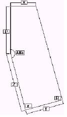
3.4.2.1 The rudder shape shall be as follows: |
| X: 175mm +0/-2 | |
Y: 260mm +0/-3 | ||
Z: 400mm +0/-2 | ||
P: 337mm +0/-2 | ||
Alfa: 165 degrees +/-1 | ||
r: Angle 90 degrees +/-1, radius 40mm (+/- 5) | ||
R: Angle 90 degrees +/-1, radius 90mm (+/- 5) | ||
The corners at each and of X shall be rounded to a radius of 4 mm +/- 1mm | ||
Between radius limits all sides shell be straight edges (+/- 2mm) |
3.4.2.2 The thickness of the rudder (excluding bevels) shall be not less than 14 mm (12 mm for wooden construction) and not more than 15 mm. | 3.4.2.2 The thickness of the rudder (excluding bevels) shall be not less than 14 mm (12 mm for wooden construction) and not more than 15 mm. | |
Bevelling is permitted between the edges and the bevelling limits, situated 60 mm from all edges. | Bevelling is permitted between the edges and the bevelling limits, situated 60 mm from all edges. | |
No bevelling is permitted on the top of the rudder head. | No bevelling is permitted on the top of the rudder head. | |
3.4.2.3 The tiller shall be removable and shall be fixed to the rudder by two metal bolts of 5 (+/- 1.5) mm diameter. | 3.4.2.3 The tiller shall be removable and shall be fixed to the rudder by two metal bolts of 5 (+/- 1.5) mm diameter. | |
The fitting connecting tiller and tiller extension is optional. | The fitting connecting tiller and tiller extension is optional. | |
Tiller, tiller extension and fittings shall have no sharp projections. | Tiller, tiller extension and fittings shall have no sharp projections. | |
3.4.2.4 The tiller and tiller extension shall each be not more than 750 mm long and their combined length shall not be more than 1200 mm. | 3.4.2.4 The tiller and tiller extension shall each be not more than 750 mm long and their combined length shall not be more than 1200 mm. | |
3.4.3 The assembled rudder, tiller and tiller extension shall float, and their total weight shall not be less than 1.5kg. | 3.4.3 The assembled rudder, tiller and tiller extension shall float, and their total weight shall not be less than 1.5kg. | |
Ballasting of any part of this assembly is prohibited. | Ballasting of any part of this assembly is prohibited. | |
3.4.4 Definition of Rudder elements | 3.4.4 Definition of Rudder elements | |
3.4.4.1 Bearing lines: two horizontal lines (parallel to the baseline) through the bearing points of the rudder fittings. | 3.4.4.1 Bearing lines: two horizontal lines (parallel to the baseline) through the bearing points of the rudder fittings. | |
3.4.4.2 Rudder head front line: line passing through the intersections of the forward edge of the rudder and the two bearing lines. | 3.4.4.2 Rudder head front line: line passing through the intersections of the forward edge of the rudder and the two bearing lines. | |
3.4.5 Fixing and positioning: Boats built before 1 March 1992 may either use the rudder positioning method which was applicable at the time of building, or the current one. | 3.4.5 Fixing and positioning: Boats built before 1 March 1992 may either use the rudder positioning method which was applicable at the time of building, or the current one. | |
The positioning fittings of the rudder themselves shall then comply with the correspondingly dated rules for the rudder. | The positioning fittings of the rudder themselves shall then comply with the correspondingly dated rules for the rudder. | |
3.4.5.1 Two pintles shall be fixed on the rudder, their diameter shall be not more than nominal 6mm. | 3.4.5.1 Two pintles shall be fixed on the rudder, their diameter shall be not more than nominal 6mm. | |
The distance between the upper edge of the tiller and the bearing line of the upper pintle shall be not less than 85 mm, measured along the rudder head frontline. | The distance between the upper edge of the tiller and the bearing line of the upper pintle shall be not less than 85 mm, measured along the rudder head frontline. | |
Two gudgeons shall be fixed to the aft transom, with holes not less than 6 mm diameter. | Two gudgeons shall be fixed to the aft transom, with holes not less than 6 mm diameter. | |
The distance between the bearing lines of the two gudgeons shall be not less than 200 mm. | The distance between the bearing lines of the two gudgeons shall be not less than 200 mm. | |
The corresponding distance between the pintles shall be not more than 200 mm. | The corresponding distance between the pintles shall be not more than 200 mm. | |
The depth of the pivoting holes in the two gudgeons shall not exceed 5 mm, and the distances from those holes to the aft face of the aft transom shall not differ by more than 2 mm. | The depth of the pivoting holes in the two gudgeons shall not exceed 5 mm, and the distances from those holes to the aft face of the aft transom shall not differ by more than 2 mm. | |
3.4.5.2 The rudder and tiller assembly shall be fitted to the aft transom so that it does not become detached from the hull during a capsize.. | 3.4.5.2 The rudder and tiller assembly shall be fitted to the aft transom so that it does not become detached from the hull during a capsize.. | |
To this effect, an appropriate retaining clip/spring shall be fitted on the forward edge of the rudder head, not less than 5 mm below the bearing line of the upper pintle.. | To this effect, an appropriate retaining clip/spring shall be fitted on the forward edge of the rudder head, not less than 5 mm below the bearing line of the upper pintle.. | |
3.4.5.3 When fitted to the aft transom, the distances from the rudder head frontline to the aft face of the aft transom, measured at the position of both bearing lines, shall be not more than 45mm and shall not differ by more than 2 mm. | 3.4.5.3 When fitted to the aft transom, the distances from the rudder head frontline to the aft face of the aft transom, measured at the position of both bearing lines, shall be not more than 45mm and shall not differ by more than 2 mm. | |
3.4.6 Rudders presented for first measurement between 1 March 2004 and 28 February 2005 may conform to either the above rules or the rules valid before 1 March 2004. | 3.4.6 Rudders presented for first measurement between 1 March 2004 and 28 February 2005 may conform to either the above rules or the rules valid before 1 March 2004. | |
Rudders presented for first measurement from 1 March, 2005 shall conform to the above rules. | Rudders presented for first measurement from 1 March, 2005 shall conform to the above rules. | |
Rudders used at the 2006 and later IODA World Sailing Championships shall conform to the above rules. | Rudders used at the 2006 and later IODA World Sailing Championships shall conform to the above rules. | |
Rudders used at the 2007 and later IODA Continental Championships shall conform to the above rules. | Rudders used at the 2007 and later IODA Continental Championships shall conform to the above rules. |
3.5 Spars | 3.5 Рангоут |
3.5.1 Materials | 3.5.1 Материалы |
3.5.1.1 The spars shall be made of either, aluminium alloy tube or, of solid wood. Wooden spars shall be of not more than two pieces of wood. Any exploitation of tolerances in order to achieve non-circular, tapered or otherwise variable spars, is prohibited. The wall thickness of the aluminium alloy tubing shall be constant throughout the spars. Internal sleeves, ribs and stiffening are prohibited. | 3.5.1.1 Рангоут должен быть изготовлен либо из трубы из алюминиевого сплава либо из массива дерева. Части деревянного рангоута должны набираться не более чем из двух деталей. Любое использование допусков в направлении достижения не круглой, заостренной формы или иные изменения элементов рангоута запрещено. Толщина стенок трубы из алюминиевого сплава должна быть постоянной на всем протяжении частей рангоута. Внутренние муфты, ребра и повышение жесткости запрещены. |
3.5.1.2 Plastic, wood or metal may be used for end caps and fittings including the boom jaws. End caps, sprit end and jaws fittings shall be permanently fixed but may be glued to the spars. The length of the fittings and cap shall not exceed 100 mm for the lower end of the mast, the outboard end of the boom and the jaws fitting, 60 mm for the top of the mast and both ends of the sprit. At the top of the mast the height of the visible part of an end cap shall not exceed 10 mm. | 3.5.1.2 Для изготовления пробок на концах рангоута и фитинга, включая усы гика может использоваться пластик, дерево или металл. Пробки, оснастка нока шпринта и усы гика должны быть твердо закреплены, но могут быть приклеены к рангоуту. Длина фитингов и пробок не должны превышать 100 мм для нижнего конца мачты, нока гика и усов, 60 мм для топа мачты и обоих концов шпринта. Высота видимой части пробки на топе мачты не должна превышать 10 мм. |
3.5.1.3 Spars shall be capable of floating approximately horizontally for thirty minutes with no discernible water penetration for a sealed spar or loss of buoyancy for a foam filled spar. | 3.5.1.3 Части рангоута должны обладать способностью оставаться на воде в горизонтальном положении в течение тридцати минут без видимого проникновения воды (для закупориваемых частей рангоута) или потери плавучести (для частей рангоута заполняемых пеной). |
3.5.1.4 Unless specifically permitted by these rules, fittings on spars shall be permanently fixed by means of rivets, screws, and/or nuts and bolts. | 3.5.1.4 Исключая случаи, когда это специально разрешено этими правилами, фитинги на рангоуте должны быть твердо закреплены посредством заклепок, винтов и/или болтов и гаек. |
3.5.1.5 Non-metallic protective material may be used on either the sprit or mast at the area where they make contact. This material shall not exceed max. 150 mm length and max. 1.5mm thickness. | 3.5.1.5 Неметаллический защитный материал может использоваться на шпринте или на мачте в области, где они соприкасаются. Этот материал не должен превышать макс. 150 мм по длине и макс. 1.5мм по толщине. |
3.5.2 Mast | 3.5.2 Мачта |
3.5.2.1 The mast shall be approximately circular in section. At any cross section the diameter shall not vary by more than 3 mm. The diameter above 50 mm from the heel shall nowhere be less than 44 mm. | 3.5.2.1 Мачта должна быть приблизительно круглой в разрезе. На любом срезе диаметр мачты не должен различаться более чем на 3 мм. Выше 50 мм от пятки мачты диаметр нигде не должен быть меньше 44 мм. |
3.5.2.2 Masts shall be of uniform section above 50mm from the heel. Wooden masts may be reinforced with a GRP or plastic collar which shall extend not more than 800mm above the heel and shall not increase the diameter by more than 4mm. | 3.5.2.2 Выше 50 мм от пятки мачты мачта должна быть одинаковой формы. Деревянные мачты могут быть усилены GRP или пластиковым воротником, который не должен выходить более чем на 800мм выше пяты мачты и не должен увеличивать диаметр мачты более чем на 4мм. |
3.5.2.3 An aluminium mast may be fitted with not more than two sleeves of GRP or plastic to allow it to fit a larger diameter mast thwart hole and mast step. Each sleeve shall be of uniform wall thickness and shall not extend along the mast for more than 50 mm. | 3.5.2.3 Алюминиевая мачта может быть снабжена не более чем двумя муфтами из GRP или пластика, что позволяет сделать их пригодными для установки в отверстие мачтовой банки и степс большего диаметра. Каждая муфта должна иметь одинаковую толщину стенок и не должна протягиваться вдоль мачты более чем на 50 мм. |
3.5.2.4 The overall length of the mast shall be not more than 2350 mm. | 3.5.2.4 Общая длина мачты не должна быть больше 2350 мм. |
3.5.2.5 Standing rigging of any sort is prohibited. | 3.5.2.5 Стоячий такелаж любого рода запрещен. |
3.5.2.6 The mast shall have either two holes, in any direction in the horizontal plane, or two eyes, which need not be permanently fixed, or one eye and one hole. The upper edge of one of the holes or eyes shall be not less than 20 mm from the top of the mast and the upper edge of the other not less than 120 mm from the top of the mast. Lacing lines shall pass through these eyes or holes and shall be lashed through the eyelet at the throat of the sail, see also CR. 6.6.3.1 A wind indicator or wind indicator fittings (CR.3.5.2.12) may secure, or be secured by these lacing lines, but this does not release the lines from the obligation of passing through the holes or eyes. | 3.5.2.6 Мачта должна иметь либо два отверстия, расположенные в любом направлении в горизонтальной плоскости, либо два рыма, которые не обязательно должны жестко закрепляться, либо один рым и одно отверстие. Верхняя граница одного из отверстий или одного из рымов должно быть не менее чем в 20 мм от топа мачты и верхняя граница другого - не менее чем в 120 мм от топа мачты. Через эти отверстия или рымы должен проводиться линь, которым через люверс в верхнем галсовом углу должен быть привязан парус, см. также ПК. 6.6.3.1 Флюгер или крепления флюгера (ПК.3.5.2.12) могут закреплять или закрепляться, этими линями, но это не исключает необходимости проводить лини через отверстия или рымы. |
3.5.2.7 Distinctively coloured bands, clearly visible while racing, and each not less than 10mm wide shall be marked on the mast as follows: | 3.5.2.7 Отчетливые окрашенные полосы, четко видимые во время гонок, каждая шириной не менее 10мм должны быть нанесены на мачту следующим образом: |
(a) Band No. 1, the lower edge of which shall be not less than 610 mm from the top of the mast. | (a) Полоса No. 1, нижняя граница которой должна находиться на расстоянии не менее чем 610 мм от топа мачты. |
(b) Band No. 2, the upper edge of which shall be not more than 635 mm from the top of the mast. | (b) Полоса No. 2, верхняя граница которой должна находиться на расстоянии не более 635 мм от топа мачты |
The lower edge of Band No. 1 and the upper edge of Band No. 2 shall be permanently marked by a scribed line or not less than two marks made with a centre punch. | Нижняя граница Полосы No. 1 и верхняя граница Полосы No. 2 должны быть устойчиво помечены чертой или не менее чем двумя метками, сделанными пробойником. |
3.5.2.8 The mast shall be positioned in the mast step by means of wedges, blocks or other devices so that it shall be unable to move more than 3 mm in any horizontal direction. The position of the heel of the mast shall not be varied while racing. | 3.5.2.8 Мачта должна быть установлена в степсе посредством клиньев, блоков или других приспособлений так, чтобы исключить возможность перемещения более чем на 3 мм в любом горизонтальном направлении. Положение пятки мачты не должно изменяться во время гонки. |
3.5.2.9 The mast shall have a cleat in a suitable position for securing the boom downhaul. | 3.5.2.9 В подходящем месте на мачте должен быть стопор для предупреждения опускания гика. |
3.5.2.10 The mast shall have, in a suitable position, for the sprit, either a cleat and one hole or eye (which need not be permanently fixed), or a toothed rack. | 3.5.2.10 В подходящем для шпринта месте, на мачте должен быть либо стопор и одно отверстие или рым, (который не обязательно должен быть жестко закреплен), или зубчатая рейка. |
3.5.2.11 A locking device or other arrangement shall be fitted and used to prevent the mast from coming out of its step when the boat is capsized. | 3.5.2.11 Замковое устройство или другое приспособление должно быть установлено и использоваться для предотвращения выхода мачты из степса при опрокидывании судна. |
3.5.2.12 A wind indicator may be fitted to the top of the mast. The mast may have a fitting (which need not be permanently fixed) for securing the wind indicator. Such a fitting shall be positioned within 150 mm below the top end of the mast and it shall have no sharp projections. The wind indicator or its attachment fittings may be used to help secure the lacing lines from the throat of the sail. | 3.5.2.12 На вершину мачты может быть установлен флюгер. Мачта может иметь крепеж для закрепления флюгера (который не обязательно должно быть закреплен жестко). Такой крепеж должен размещаться в пределах 150мм от топа мачты и не должен иметь острых выступающих частей. Флюгер или его крепление могут использоваться в качестве вспомогательного крепежа для линей переднего галсового угла паруса. |
3.5.2.13 The mast may have a pin stop positioned on the forward side of the mast 1680 mm +/- 10mm below the top end of the mast. This pin shall not be more than 8 mm diameter and within 10 mm of the surface of the mast and shall have no sharp projections. | 3.5.2.13 На передней стороне мачты в 1680 мм +/- 10мм ниже топа мачты может быть стопорный палец. Диаметр этого пальца не должен быть более 8 мм, он не должен выступать более чем на 10 мм от поверхности мачты и не должен иметь острых выступающих частей. |
3.5.3 Boom | 3.5.3 Гик |
3.5.3.1 The boom shall be approximately circular and of uniform section throughout. The diameter shall be not less than 25 mm and at any section it shall not vary by more than 3 mm. | 3.5.3.1 Гик должен быть приблизительно круглым в разрезе и иметь одинаковую форму везде. На любом срезе диаметр гика должен быть не менее 25мм и не должен различаться более чем на 3 мм. |
3.5.3.2 The boom, excluding the boom jaws, shall not exceed 2057 mm in length. | 3.5.3.2 Гик, исключая усы гика, не должен превосходить 2057 мм в длину. |
3.5.3.3 The type of boom jaws and jaws fitting is optional but thickness of the jaws shall not exceed 35mm and the length of the jaws fittings shall not exceed 100 mm. A rope may be fastened to the boom jaws or jaws fittings through two holes or through two eyes, and pass forward, around and over a pin positioned on the forward surface of the mast (See also CR 3.5.2.13). | 3.5.3.3 Тип усов на гике и посадочные детали усов произвольные, но толщина усов не должна превышать 35мм и длина усов не должна превышать 100 мм. Веревка может быть прикреплена к усам гика или крепежу усов через два отверстия или через два рыма, и проведена, вокруг и через палец, расположенный на передней стороне мачты (см. также ПК 3.5.2.13). |
3.5.3.4 A distinctively coloured band, clearly visible while racing, and not less than 10 mm wide shall be marked on the boom with its forward edge not more than 2000 mm from the aft edge of the mast. The inner edge of the band shall be permanently marked by a scribed line or not less than two marks made with a centre punch. The coloured band at the outboard end of the boom may be on a permanently fixed end cap, provided that no visible part of the end cap extends inward of the position of the forward edge of the band, and that the cap complies with the former part of this rule, and with class rule 3.5.3.2. | 3.5.3.4 Отчетливая окрашенная полоса, четко видимая во время гонок, шириной не менее 10мм должна быть нанесена на гике. Ее передняя граница должна быть не более чем в 2000 мм от нокового конца гика. Внутренняя граница полосы должна быть устойчиво помечена чертой или не менее чем двумя метками, сделанными кернером. Окрашенная полоса на ноковом конце гика может быть на устойчиво закрепленной пробке, обеспечивающей, что видимая часть пробки заходит внутрь позиции передней границы полосы, и что пробка соответствует прежним положениям этого правила, и правилу 3.5.3.2. |
3.5.3.5 Either the boom or the end cap shall have a hole or lacing eye. The forward edge of the hole or the opening of the eye shall be not more than 40 mm from the inner edge of the band at the outboard end of the boom. band at the outboard end of the boom. | 3.5.3.5 На гике или на пробке нока гика должно быть отверстие или рым. Передняя граница отверстия или просвета рыма должны быть не более чем в 40мм от внутреннего края полосы на внешнем конце гика. |
3.5.3.6 A cleat with no sharp projections for securing a clew outhaul may be fitted on the boom. It shall be not less than 400 mm from the outer end of the boom. | 3.5.3.6 На гике может быть установлен стопор без острых углов для закрепления оттяжки шкотового угла грота. Он должен располагаться не менее чем в 400мм от нока гика. |
3.5.3.7 The boom downhaul may be attached to the boom in an optional manner by use of a fixed stop or lacing eye at a fixed position. The outer edge of the fitting used shall not be more than 200 mm from the inner end of the boom excluding boom jaws. | 3.5.3.7 Оттяжка грота может быть закреплена к гику произвольным способом с использованием фиксированного упора или скобы в закрепленном положении. Внешняя граница используемого крепежа должна быть не более чем в 200 мм от пятки гика, исключая усы гика. |
3.5.3.8 The method of attachment of the mainsheet or mainsheet block(s) to the boom is optional (provided they cannot slip along the boom, and the maximum clearance between the span and the boom shall be not more than 100 mm, at any position along the boom). The position of the blocks or the length of boom strops shall not be adjusted while racing. | 3.5.3.8 Способ крепления гика-шкотов или блока(ов) гика-шкотов произвольный (обеспечивающий, чтобы они не могли перемещаться вдоль гика и максимальный просвет между используемой снастью и гиком не должен превышать 100мм в любом месте гика). Положение блоков или длина стропов гика не должна подстраиваться во время гонки. |
3.5.3.9 There shall not be any fitting, rigging or device the purpose of which is, or may be, to control the position of the boom on the mast except for items specifically required or permitted by these rules. | 3.5.3.9 Не должно быть какого-либо крепежа, снаряжения или устройств, предназначением которых является или может быть контроль положения гика на мачте исключая те, что специально требуются или разрешены настоящими требованиями. |
3.5.4 Sprit | 3.5.4 Шпринт |
3.5.4.1 The sprit shall be approximately circular and of uniform section throughout. Its diameter shall be not less than 24 mm and in any section it shall not vary by more than 3 mm. | Шпринт должен быть приблизительно круглым в разрезе и иметь одинаковую форму разреза по всей длине. Его диаметр должен быть не менее 25мм и на любом срезе не должен различаться более чем на 3 мм. |
3.5.4.2 The sprit shall be not more than 2286 mm in length, including end fittings. | 3.5.4.2 Длина шпринта, включая фитинги, не должна превосходить 2286 мм. |
3.5.4.3 The type of fitting at the upper end of the sprit shall be as shown in the rigging plan. If the upper end fitting exhibits a widening after an initial narrowing, this widening shall not be in excess of 13 mm. | 3.5.4.3 Тип оснастки на нокбензельном конце шпринта должен быть таким, как показано на Чертеже рангоута. Если верхний конец оснастки имеет расширение после суженной начальной части, это расширение не должно превосходить 13 мм. |
The fitting at the lower end of the sprit shall be either one of the fittings permitted at its upper end, or the sprit may be fitted with an eye, a hook, or it may have a hole through the spar. | Оснастка на нижнем конце шпринта должна быть либо такой, как оснастка, разрешенная для нокбензельного угла, либо шпринт может быть снабжен рымом или крюком, либо иметь сквозное отверстие. |
The length of the end fittings on both ends shall not exceed 60 mm. The eye, hook or hole at the lower end of the sprit if present, shall be located within 60 mm of this end. | Длина оснастки на обоих концах шпринта не должна превышать 60мм. Рым, крюк или отверстие на нижнем конце шпринта должны располагаться не далее 50мм от этого конца. |
3.5.5 Running Rigging | 3.5.5 Бегущий такелаж. |
3.5.5.1 The mainsheet arrangement is optional except as controlled by CR 3.2.6.1 and CR 3.5.3.8. | 3.5.5.1 Крепление грота произвольное, исключая требования определенные ПК 3.2.6.1 и ПК 3.2.6.1 |
3.5.5.2 Downhaul. A single part downhaul of rope and/or wire shall be fitted to the boom not more than 200 mm from the inner edge of the boom jaws. It shall be secured to a cleat on the mast. | 3.5.5.2 Оттяжка гика. Оттяжка гика, состоящая из цельного куска веревки и/или проволоки, должна быть закреплена на гике не более чем в 200мм от конца усов гика. Она должна быть закреплена к стопору на мачте. |
The downhaul shall not be adjustable from aft of the midship frame. | Оттяжка гика не должна регулироваться с кормового конца мидель - шпангоута. |
3.5.5.3 Only the lower end of the sprit shall be made fast to the mast. The only methods of attachment and adjustment of the lower end of the sprit shall be by means of: | 3.5.5.3 Только нижний конец шпринта должен крепиться к мачте. Крепление и регулировка нижнего конца шпринта выполняется только следующими способами: |
(a) A rope or wire rope loop in conjunction with a toothed rack. The maximum dimensions of the toothed rack are: | (a) Веревочная или тросовая петля в соединении с зубчатой рейкой. Максимальные размеры зубчатой рейки: |
Length 150 mm | Длина 150 мм |
Width 20 mm | Ширина 20 мм |
Thickness 3 mm | Толщина 3 мм |
Height of tooth 10 mm | Высота зубьев 10 мм |
or | Или |
(b) A halyard consisting of not more than two parts of rope or rope/wire combination, with no more than two single sheave blocks, to obtain no more than a double “Purchase” plus one hole or one eye, and one cleat which are fastened on the mast. The way of attaching the blocks on the lower end of the sprit or on the mast is optional. The sprit shall not be adjustable from aft of the mid-ship frame. | (b) Гардель, состоящая не более чем из двух отрезков веревки или комбинации веревки/проволоки, не более чем с двумя одношкивными блоками, для получения не более чем двойного “выигрыша в силе”, плюс одно отверстие или один рым, и один стопор, которые закрепляются на мачте. Способ крепления блоков на нижнем конце шпринта или на мачте произвольный. Шпринт не должен регулироваться с кормового конца мидель - шпангоута. |
3.5.5.4 Outhaul. The outhaul shall be made of rope, and consist of a single material. It may be adjustable. In this case it shall use no more than two purchases; no blocks are allowed; and the outhaul end shall then pass through the hole or lacing eye near the end of the boom (see also CR 3.5.3.5) and be secured to the outhaul cleat on the boom. | 3.5.5.4 Гроташкот. Гроташкот должен быть изготовлен из веревки, и содержать один цельный отрезок. Он может быть регулируемым. В этом случае должно использоваться не более двух лопарей; использование блоков не разрешено; конец гроташкота должен затем проходить через отверстие или рым вблизи конца гика (см. также ПК 3.5.3.5) и закрепляться к стопору гроташкота на гике. |
3.5.5.5 The use of wire is prohibited except for the boom downhaul, sprit halyard and strops on the boom for fitting sheet blocks. | 3.5.5.5 Использование проволоки запрещено за исключением оттяжки гика, гардели шпринта и стропы на гике для крепления шкотовых блоков. |
3.5.5.6 No running rigging shall be allowed inside of hollow spars. | 3.5.5.6 Проводка бегущего такелажа внутри пустотелых частей рангоута не допускается. |
4 ADDITIONAL RULES | 4 ДОПОЛНИТЕЛЬНЫЕ ПРАВИЛА |
4.1 Only one person shall be on board while racing | 4.1 Только один человек должен быть на лодке во время гонки |
4.2 | 4.2 |
(a) The helmsman shall wear adequate personal buoyancy. All fastening devices supplied by the manufacturer shall be used in the manner intended. Wet suits and dry suits do not constitute personal buoyancy | (a) Гонщик должен одеть персональное спасательное средство. Все представленные производителем элементы обеспечивающие его крепление должны использоваться как предназначено. Влажный и сухой гидрокостюмы не назначаются средствами персональной защиты. |
(b) With reference to the Racing Rules of Sailing the total weight of clothing and equipment worn or carried by a competitor, excluding footwear shall not be capable of exceeding 8 kg when weighed as provided in Appendix J of the Racing Rules. | (b) В соответствии с Правилами Парусных Гонок. общий вес одежды и снаряжения носимой гонщиком, исключая обувь не должен иметь возможности превышать 8 кг, при условии, когда взвешивание выполняется, как представлено в приложении J Правил Гонок |
(c) Hiking pants, not attached to the boat and not containing any stiffening which can extend below the knee joint, are permitted irrespective of whether they would otherwise contravene RRS 49.1. | (c) Откренки, не закрепленные на судне и не содержащие сплошных элементов жесткости, которые могут протягиваться ниже колена, разрешены безотносительно тому, что они будут иначе противоречить RRS 49.1. |
4.3 The following equipment shall be on board while racing | 4.3 Следующее оборудование должно быть на борту во все время гонок |
(a) One or more bailers which shall be securely attached to the hull by a lanyard(s) One bailer shall have a minimum capacity of one litre | (a) Один или более черпаков, которые должны быть надежно прикреплены к корпусу шнуром (ами) Один черпак должен иметь минимальную емкость 1 л. |
(b) A painter of a single piece of buoyant rope, not less than 5 mm diameter and not less than 8 m long securely fastened to the mast thwart or mast step. (see also 3.2.6.1) | (b) Буксирный конец из одного куска плавучей веревки, диаметром не менее 5 мм и длинной не менее 8м надежно закрепленной к мачтовой банке или степсу мачты. (см. также 3.2.6.1) |
4.4 An anchor need be carried only when specifically prescribed in the sailing instructions | 4.4 Якорь необходимо нести только когда это специально предписано в гоночных инструкциях |
4.5 A paddle, secured to the hull, need be carried only when prescribed in the sailing instructions. | 4.5 Весло, закрепленное на корпусе необходимо нести только когда это предписано в гоночных инструкциях. |
4.6 Unless damage renders a hull, sail, spar or foil unusable during an event, only one hull, sail, mast, boom, sprit, daggerboard and rudder shall be used throughout the event. Any such change of equipment shall be authorised by the Race Committee | 4.6 За исключением случаев повреждения, корпуса, паруса, вооружение или доски не используемы во время гонок, только один корпус, парус, мачта, гик, шпринт, шверт, и перо руля должны использоваться во все время мероприятия. Любые подобные замены оборудования должны быть одобрены Гоночным Комитетом |
4.7 If there is a national Optimist Class Association of the country in which the boat is registered the owner shall be a member. Where a boat is sailing in an international regatta the competitor shall be a member of a national Optimist association or other body which is itself a member of the I. O.D. A as defined in IODA Article 3 (a) | 4.7 Если имеется национальная ассоциация класса Оптимист страны, в которой судно зарегистрировано, владелец должен быть ее членом. Там где судно участвует в гонках в международной регате участник соревнования должен быть членом национальной ассоциации класса Оптимист или другой организации, которая сама является членом I. O.D. A как определено в IODA параграфе 3 (a) |
6 SAIL | 6 ПАРУС |
6.1 General | 6.1 Общие положения |
6.1.1 Sails shall comply with the class rules in force at the time of certification unless otherwise specified below. | 6.1.1 Паруса должны соответствовать правилам класса, действующим на момент сертификации, исключая случаи описанные ниже. |
6.1.2 Anything not specifically permitted by these rules is prohibited, see also CR. 1.2. | 6.1.2 Все. Что специально не разрешено этими правилами - запрещено (см. правило 1.2.) |
6.1.3 Sails shall be made and measured in accordance with the current ISAF “Equipment Rules of Sailing” as applicable to Optimist sails, except where varied herein. | 6.1.3 Паруса должны быть изготовлены и обмерены в соответствии с действующими «Правилами по парусному снаряжению» ИСАФ, применимых в отношении парусов класса Оптимист, исключая приведенные здесь отличия. |
Where a term defined or measurement given in these ISAF Rules is used in these rules, it is printed in “italic” type. | Там где термины или измерения приведенные в этих правилах IASF использованы в этих правилах они печатаются фонтом «Италик». |
All measurements shall be taken along the surface of the sail and include any bolt rope and tabling. | Все измерения должны выполняться вдоль поверхности паруса и включать любые ликтросы и обшивку (tabling). |
Battens shall not be removed for sail measurement purposes. | Латы не должны извлекаться для измерения паруса. |
6.1.4 Certification | 6.1.4 Сертификация |
6.1.4.1 A measurer approved by an MNA or a class association where so authorised by an MNA shall certify the sail in the tack and shall sign and date the certification mark. | 6.1.4.1 Меритель, уполномоченный MNА или ассоциацией класса где так уполномочен MNA должен сертифицировать парус в галсовом углу и должен подписаться и указать дату отметки сертификации |
6.2 Sail maker | 6.2 Производитель парусов. |
6.2.1 No Licence is required | 6.2.1 Лицензия не требуется. |
6.2.2 The thickness of the body of the sail shall not be less than 0.15mm. | 6.2.2 Толщина тела паруса не должна быть меньше 0.15 мм. |
Where in the construction of the body of the sail the cloth is of variable thickness, the thinnest parts of the sail as measured by a micrometer with a spindle surface of 6.4mm (+-0.25mm) diameter shall each be at least 9mm x 9mm square, and the thickness of the cloth shall be deemed to be that of the thinnest parts. Sails, which are not so constructed, shall cease to comply with Class Rules from 1 March 2005 and shall not be permitted for use at IODA events from 1 March 2005 | Там, где в конструкции паруса ткань различной толщины, самые тонкие части паруса, измеренные микрометром с диаметром поверхности шпинделя 6.4мм (+-0.25мм), должны быть, по крайней мере, 9*9мм2 каждая и толщина ткани должна быть полагающаяся в самых тонких частях. Паруса, сконструированные иначе, не будут отвечать Правилам Класса с 1 марта 2005г и не должно допускаться использовать их на мероприятиях IODA с 1 марта 2005г. |
The thickness in mm of the body of the sail shall be indelibly marked by the manufacturer, together with his signature, stamp, and date near the peak point. | Толщина тела паруса в мм. должна быть нанесена производителем на парус несмываемым красителем вместе с подписью, штампом и датой около нокбензельного угла. |
6.3 Mainsail | 6.3 Грот |
6.3.1 Identification | 6.3.1. Опознавательный знак |
6.3.1.1 The class insignia shall conform to the dimensions and requirements detailed in the diagram in CR 2.7.1 and be placed in accordance with the diagram contained in Sail Plan Sheet 4/5. No part of the class insignia shall extend beyond 1000mm of the peak point. The class insignia shall be placed back to back on both sides of the sail | 6.3.1.1 Знак класса должен соответствовать измерениям и требованиям, подробно описанным на диаграмме в ПК 2.7.1, и расположен в соответствии с диаграммой содержащейся на чертеже паруса 4/5. Знак класса не должен выходить за границу окружности радиусом 1000мм от нокбензельного угла. Знаки класса должны располагаться спина к спине на обеих сторонах паруса. |
6.3.2 Materials The ply fibres shall be of polyester or cotton. The manufacturer of sail battens is optional. The construction material is optional except that Carbon fibre is prohibited. | 6.3.2 Материалы. Нити полотнища должны быть из полиэстера или хлопка. Производитель лат не обязателен. Материал изделия не обязателен, исключая то, что карбоновое волокно запрещено. |
6.3.3 Construction | 6.3.3 Конструкция |
6.3.3.1 The construction shall be: soft sail, single ply sail. | 6.3.3.1 Конструкция паруса должна быть: мягкий парус, парус одно-полотно. |
6.3.3.2 The body of the sail shall consist of the same woven ply throughout | 6.3.3.2 Тело паруса должно целиком состоять из одного полотнища ткани. |
6.3.3.3 The sail shall have two batten pockets in the leech. Local widening for batten insertion (if any) shall be on the upper edge of the batten pockets. The outer end of the batten pockets shall be parallel to the leech at that point. | 6.3.3.3 Парус должен иметь два лат-кармана на задней шкаторине. Расширения для вставки лат (если есть) должны располагаться на верхнем углу лат-карманов. Внешний конец лат-карманов должен быть параллелен задней шкаторине в этой точке. |
6.3.3.4 The leech shall not deviate more than +5/-10mm from a straight line between: | 6.3.3.4 Задняя шкаторина не должна отклоняться более чем на +5/-10 мм от прямой линии между: |
a. The peak point and the intersection of the leech and the upper edge of the top battenpocket. | а. Вершиной и пересечением задней шкаторины и верхней кромки верхнего латкармана. |
b. The intersection of the leech and the lower edge of the top batten pocket and the intersection of the leech and the upper edge of the lower batten pocket and, | в. Пересечения шкаторины и нижней кромки верхнего лат-кармана и пересечения задней шкаторины и верхней кромки нижнего лат-кармана и |
c. The clew point and intersection of the leech and the lower edge of the lower batten pocket. | с. Шкотового угла и пересечения задней шкаторины и нижней кромки нижнего лат-кармана. |
Sails, which do not comply with Rule 6.3.3.4, shall not be used after 1 March 2005. | Паруса, не соответствующие правилу 6.3.3.4, не должны использоваться после 1 марта 2005г. |
6.3.3.5 The leech shall not deviate more than +20/-5mm from a straight line between the intersection of the leech and the lower edge of the top batten pocket and the clew point. | 6.3.3.5 Задняя шкаторина не должна отклоняться более чем на +20/-5мм от прямой линии между пересечением задней шкаторины и нижнего обреза верхнего лат-кармана и шкотового угла. |
Sails presented for first measurement after 1 March 2005 shall comply with this rule. | Паруса, впервые обмеряемые после 1 марта 2005, должны отвечать этому правилу. |
6.3.3.6 The following are permitted: stitching, glues, bolt ropes, tabling, 2 batten pockets, batten pocket elastic, batten pocket patches, flutter patches, one trapezoidal window, sail maker label, sail button(s), tell tales. | 6.3.3.6 Следующее разрешено: прошивки, склейки, ликтросы, обшивка (tabling), два лат-кармана, эластичная оттяжка латкармана, усиления лат-карманов (batten pocket patches), накладки усиления задней шкаторины (flutter patches), одно трапецеидальное окно, знак производителя паруса, парусная кнопка (ки), колдунчики |
Primary reinforcements shall be made of woven ply of any thickness. The ply fibres shall be made of polyester or cotton. Secondary reinforcements shall be made from the same woven ply as the body of the sail, with the exception that batten pocket patches and flutter patches may be made from a woven cotton or polyester ply, thinner than that of the body of the sail. | Первичные усиления должны быть сделаны из слоя ткани любой толщины. Волокна ткани должны быть изготовлены из полиэстера или хлопка. Вторичные усилители должны быть изготовлены из той же ткани, что и парус, исключая накладки усиления лат-карманов и накладок усиления задней шкаторины (flutter patches), которые могут быть сделаны из хлопковой или полиэстеровой ткани более тонкой, чем парус. |
Edges of secondary reinforcements shall be fixed by a maximum of two lines of stitches or bonding agents. Parallel or nearly parallel lines of stitching or bonding agent used elsewhere in the secondary reinforcement shall be more than 40mm apart. If two rows of closely positioned stitching are used to fix the edge of the secondary reinforcement then any inner lines of parallel stitching shall be more than 40mm distant from the inner line of edge stitching. Tabling shall be either by folds of the body of the sail or of separate polyester or cotton material not thinner than the body of the sail. Further to CR 1.2 and 6.1.2, the following are prohibited: carbon fibres, titanium. | Углы вторичных усилителей должны быть закреплены максимально двумя швами или креплениями. Параллельные или субпараллельные линии стежков или крепления, используемые где-либо на парусе должны располагаться на расстоянии более 40 мм. |
6.3.3.7 Wire or elastic cord shall not be used in the sail. Any bolt rope or tabling used to strengthen the luff or head of the sail shall be fastened to the sail throughout its entire length. If a boltrope is enclosed in the tabling, it shall be sewn to the sail by visible stitches at those corners of the sail to which the rope extends. No boltrope is permitted in the leech or foot. | В конструкции паруса не должны использоваться проволока или эластичный шнур. Любой ликтрос или обшивка (tabling), используемы для усиления передней или верхней шкаторины, должны быть закреплены к парусу по всей длине. Если ликтрос заключен в обшивку (tabling), она должна быть пришита к парусу видимыми стежками на тех углах паруса к которым веревка протянута. Не разрешается ликовка задней и нижней шкаторин. |
6.3.3.8 There shall be eight eyelets in the foot of the sail, including those at the tack and clew. There shall be eight eyelets in the luff of the sail, including those at the throat and tack. (see also rule 6.4 for spacing between eyelets in luff and foot). | 6.3.3.8 В нижней шкаторине паруса должно быть восемь люверсов, включая люверсы на нижнем галсовом и шкотовом углах.. В передней шкаторине паруса должно быть восемь люверсов, включая люверсы на нижнем галсовом и верхнем галсовом углах (для определения расстояния между люверсами на передней и нижней шкаторинах смотри так же правило 6.4). |
6.4 Dimensions | 6.4 Размеры |
Minimum Maximum | Минимум Максимум |
1 Leech length 2800 mm | 1. Длина задней шкаторины 2800мм |
2 Head length 1240 mm | 2. Длина верхней шкаторины 1240мм |
3 Diagonal 2450 mm 2580 mm | 3. Диагональ 2460мм 2580мм |
4 Half width 1700 mm | 4 Ширина паруса на 1/2 высоты 1700 мм |
5 Foot Mid-point to throat point 2130 mm | 5 Расстояние от середины нижней шкаторины до верхнего галсового угла. 2130 мм |
6 Luff length 1730 mm | 6 Длина передней шкаторины 1730 мм |
7 Width of luff measurement band 5 mm | 7 Ширина мерной ленты передней шкаторины 5 мм |
8 Length of luff measurement band 60 mm | 8 Длина мерной ленты передней шкаторины 60 mm |
9 Upper edge of luff measurement band to throat point 600 mm | 9 Расстояние от верхней кромки мерной ленты передней шкаторины до верхнего галсового угла 600 мм |
10 Thickness of woven ply anywhere in the body of the sail 0.15 mm | 10 Толщина ткани по всему парусу 0.15 мм |
11 Primary reinforcements: from corner measurement points 205 mm | 11 Первичные усиления от угловых обмерных точек 205 mm |
12 Secondary reinforcements: from corner measurement points 615 mm | 12 Вторичные усиления от угловых обмерных точек 615 mm |
13 Batten pocket patches at each end of batten pockets 150 mm | 13 Накладки на обоих концах лат-карманов 150 мм |
.14 Flutter patches 150 mm | .14 Накладки усиления задней шкаторины 150 мм |
15 Tabling width 40 mm | 15 обшивка (tabling) ширина 40 мм |
16 Seam width 15 mm | 16 Ширина швов15 мм |
17 Trapezoidal window opening area 0.1 m2 | 17 Открытая площадь трапецеидального окна 0.1 м2 |
18 Shortest distance from window to any edge of sail 150 mm | 18 Кратчайшее расстояние от окна до любой кромки паруса 150 mm |
19 Batten pocket length (outside) 460 mm | 19 Длина лат-карманов (снаружи) 460 мм |
20 Batten pocket width (outside) 40 mm | 20 Ширина лат-карманов (снаружи) 40 mm |
21 Peak point to intersection of leech and lower edge of uppermost batten pocket 900 mm 1000 mm | 21 От нок-бензельного угла до пресечения задней шкаторины и нижней кромки верхнего лат-кармана 900 мм 1000 мм |
22 Peak point to intersection of leech and lower edge of lowermost batten pocket 1850 mm 1950 mm | 22 От нок-бензельного угла до пресечения задней шкаторины и нижней кромки нижнего лат-кармана 1850 мм 1950 мм |
23 Deviation from straight line between peak point and upper corner of upper batten pocket - 10 mm + 5 mm | 23 Отклонение от прямой линии между нок –бензельным углом и верхним углом верхнего лат-кармана - 10 мм + 5 мм |
24 Deviation from straight line between the upper corner of upper batten pocket and lower corner of lower batten pocket - 10 mm + 5 mm | 24 Отклонение от прямой линии между верхним углом верхнего лат-кармана и нижним углом нижнего лат-кармана - 10 мм + 5 мм |
25 Deviation from straight line between lower corner of lower batten pocket and clew point - 10 mm + 5 mm | 25 Отклонение от прямой линии между нижним углом нижнего лат-кармана и шкотовым углом - 10 мм + 5 мм |
26 Deviation from straight line between the lower corner of the upper batten pocket and clew point - 5 mm + 20 mm | 26 Отклонение от прямой линии между нижним углом верхнего лат-кармана и шкотовым углом - 5 мм + 20 мм |
27 Space between luff eyelets 230 mm 260 mm | 27 Расстояния между люверсами на передней шкаторине 230 мм 260 мм |
28 Space between foot eyelets 270 mm 300 mm | 28 Расстояния между люверсами на нижней шкаторине 270 мм 300 мм |
29 Foot irregularity 15 mm | 29 Нижней шкаторины отклонения от нормы 15 мм |
6.5 Class Insignia, National Letters and Sail Numbers, Luff Measurement Band | 6.5 Символ класса, национальные символы, номер паруса, марка на передней шкаторине |
6.5.1 Numbers and letters on sails first measured after 1 March 1994 shall be of the following dimension (see also Sail Plan sheet 4/5) | 6.5.1 Номера и буквы на номерах впервые измеряемых после 1 марта 2005 года должны быть следующих размеров (см. Также чертеж паруса лист 4/5) |
minimum минимум | maximum максимум | ||
1 Height | 230 mm | 240 mm | 1. Высота |
2 Width (except “1” or “I”) | 150 mm | 160 mm | 2. Ширина (исключая «1» или «I») |
3 Width for M and W | 160 mm | 170 mm | 3. Ширина для M и W |
4 Thickness | 30 mm | 40 mm | 4. Толщина |
The national letters shall be placed on the same line on opposite sides of the sail with letters on the starboard side of the sail closer to the luff than those on the port side of the sail (see also Sail Plan sheet 4/5).The numbers shall be placed in two rows below the letters with the starboard side numbers uppermost. The following spacing shall apply | Национальные символы должны располагаться на одной линии на противоположных сторонах паруса при том что буквы на левой стороне ближе к передней шкаторине, чем на правой (см. Также чертеж паруса лист 4/5). Номера должны быть расположены в две строки ниже букв при том что на левой стороне номера выше. Следующие расстояния должна использоваться | ||
Minimum минимум | Maximum максимум | ||
5 Space between adjoining numbers or letters | 40 mm | 50 mm | 5. Расстояние между соседними номерами или буквами |
6 Space between rows of numbers or letters | 40 mm | 50 mm | 6. Расстояние между строками номеров или букв |
7 Space between the national letter groups on opposite sides of the sail | 100 mm | 150 mm | 7. Расстояние между группами национальных символов на противоположных сторонах паруса |
8 Distance between the luff and the closest letter or number in each row | 150 mm | 8 Расстояние между передней шкаториной и ближайшей буквой или цифрой в каждой строке | |
9 Distance between lower edge of uppermost batten pocket and the national letter which is closest to the leech | 40 mm | 50 mm | 9 Расстояние между нижним обрезов верхнего лат-кармана и национальными символами ближайшим к передней шкаторине |
10 Distance between number closest to the leech and the leech: as per RRS Appendix G1.2(b). | 10 Расстояние между задней шкаториной и ближайшим номером как в ППГ Прил. G1.2(b) |
6.5.2 The sail shall have a sail measurement band on its luff (luff measurement band). This band, of a colour that strongly contrasts with the sail, shall be permanently fixed or marked on both sides of the sail. It shall be perpendicular to the edge of the luff of the sail, and shall start at its edge. See CR. 6.2.2, Sail Plan, Rigging Plan sheet 12/12, for position and dimension of bands. | 6.5.2 Парус должен иметь мерную марку на передней шкаторине (мерная марка передней шкаторины). Эта лента, цвета сильно отличающаяся по цвету от паруса, должна быть прочно закреплена или нанесена на обеих сторонах паруса. Она должна располагаться перпендикулярно к кромке передней шкаторине паруса и должна начинаться на его краю. Расположение и размеры марок смотри ПК. 6.2.2, Чертеж паруса, чертеж рангоута лист 12/12,. |
6.6 Additional rules | 6.6 Дополнительные правила |
6.6.1 Only sails endorsed in accordance with CR. 2.5.6 shall be used | 6.6.1 Должны использоваться только паруса имеющие отметку мерителя в соответствии с правилом 2.5.6 |
6.6.2 Fastening and positioning | 6.6.2 Крепление и расположение |
6.6.2.1 The upper edge of the luff measurement band shall not extend above the lower edge of Band No. 1, and the lower edge of the luff measurement band shall not extend below the upper edge of Band No. 2. At the throat, both mast holes or lacing eyes referred to in CR. 3.5.2.6 shall be used to prevent any part of the luff measurement band rising above the lower edge of Band No. 1. | 6.6.2.1 Верхняя кромка мерной марки передней шкаторины не должна выходить выше нижней кромки Марки No. 1, и нижняя кромка мерной ленты передней шкаторины не должна выходить ниже верхней кромки Марки No. 2. На верхнем галсовом углу, оба отверстия мачты или скобы упомянутые в ПК. 3.5.2.6 должны использоваться для предотвращения того, чтобы какая-либо часть мерной ленты передней шкаторины возвышалась над нижней кромкой Марки No. 1. |
6.6.2.2 No part of the clew point shall extend beyond the inner edge of the boom band | 6.6.2.2 Части шкотового угла не должны выходить за пределы внутренней кромки марки на гике. |
6.6.2.3 The luff of the sail shall be lashed to the mast at each eyelet so as to be within 10 mm of the mast. | 6.6.2.3 Передняя шкаторина паруса должна быть прикреплена к мачте в каждом люверсе. так, чтобы быть не далее 10мм от мачты |
6.6.2.4 The foot of the sail shall be lashed to the boom at each eyelet so as to be within 10 mm of the boom. Alternatively, at the tack eyelet, it may either be lashed to the jaw fittings or attached through two holes in the jaws or jaw fittings, so as to be within 10 mm of the boom or its imaginary extension (see also Rigging Plan sheet 12/12). | 6.6.2.4 Нижняя шкаторина паруса должна быть привязана к гику в каждом люверсе так, чтобы быть не далее 10мм от гика. В люверсе галсового угла, он может быть либо привязан к фитингам усов либо прикреплен через два отверстия в усах или фитингах усов, чтобы быть не далее 10мм от гика или его воображаемого продолжения (см. чертеж рангоута лист 12/12). |
6.6.2.5 The sail shall be fastened to the mast and boom with cordage only. | 6.6.2.5 Парус должен прикрепляться к мачте и гику только веревкой. |
6.6.2.6 The peak of the sail shall be fastened to the upper end of the sprit either by means of an eyelet at the peak, or by means of a loop made of tape or rope sewn to the peak. | 6.6.2.6 Вершина паруса должна быть прикреплена к верхнему концу шпринта либо за люверс на нок-бензельном углу паруса, либо бензелем, сделанным из ленты или шнура пришитого на нок-бензельном углу. |
APPENDIX A
CLASS RULES SPECIFIC TO WOOD AND WOOD/EPOXY HULLS

|
Из за большого объема этот материал размещен на нескольких страницах:
1 2 3 |
