

Партнерка на США и Канаду по недвижимости, выплаты в крипто
- 30% recurring commission
- Выплаты в USDT
- Вывод каждую неделю
- Комиссия до 5 лет за каждого referral
Channel Scan List, MHz: This will confine scanning only to the selected channels (applicable to Station and Station WDS mode only). The benefits of this are faster scanning as well as filtering out unwanted AP's in the results. Site Survey tool will look for the Access Points in selected channels only.
Channel Scan list selection on NanoStation M2,country:Chile
Channel list management for the selected IEEE 802.11 mode and specified Channel Spectrum Width can be enabled by selecting the Enabled option. There are two ways to set the Channel Scan List - enumerating the required channels (separated by comma) in the input field or using the selection options in Channel Scan List window, which is activated using the Edit button. Site Survey tool will look for the Access Points in selected channels only if the scan or site survey operation is performed in Station mode.
Antenna Gain:specifies the gain of the antenna installed in the AP (applies only to devices with external antenna connector, such as Rocket and Bullet). When “Obey Regulatory Rules” is enabled, the antenna gain calculates the TX power backoff needed to remain in compliance with local regulations. This feature is complementary to the “Cable Loss” feature; and both affect the TX power of the unit.
Cable Loss: When “Obey Regulatory Rules” is enabled, the Cable Loss affects the TX power of the unit. In case you have high amounts of cables loss, the higher TX power may be increased while being in compliance with the maximum TX power allowed by the local authority. This feature is complementary to the “Antenna Gain” feature.
Output power and Obey regulatory power
Output Power: This will configure the maximum average transmit output power (in dBm) of the wireless device. The output power at which wireless module transmits data can be specified using the slider. When entering output power value manually, the slider position will change according to the entered value. The transmit power level maximum is limited according to the country regulations. If the AirOS v5.2 based device has an internal antenna (i. e. NanoStation M/LocoStation M), Output Power is the output power delivered to the internal antenna.
Obey regulatory Rules option must remain enabled while it will force the transmit output power to be compliant with the regulations of the selected country. In this case, it will not be possible to set equivalent isotropic radiated power (EIRP) above the amount allowed per regulatory domain (different maximum output power levels and antenna gains are allowed for each IEEE 802.11a/b/g/n regulatory domain thus country). For more regulatory information, please consult 802.11 compliance guide.
Wireless Data rate
Max Data Rate, Mbps: This defines the data rate (in Mbps) at which the device should transmit wireless packets. You can fix a specific data rate between MCS 0 and MCS 7 (or MCS15 for 2x2 chains devices) also. It is recommended to use automatic option, especially if you are having trouble getting connected or losing data at a higher rate. In this case, the lower data rates will be used by the device automatically. If you select 20MHz Channel Spectrum width the maximum data rate is MCS7 (65Mbps) or MCS15 (130Mbps). If you select 40MHz Channel Spectrum width the maximum data rate is MCS7 (150Mbps) or MCS15 (300Mbps).
Note: In case you have selected WEP, WPA-TKIP or WPA2-TKIP security method, the maximum data rate is MCS12. This is a hardware limitation due to the Atheros HAL. Should you need a higher data rate try using WPA-AES or WPA2-AES.
Automatic: When the Automatic checkbox is selected, the rate algorithm will select the best data rate, depending on link quality conditions. It is recommended to use the automatic option, especially if you are having trouble getting connected or losing data at a higher rate. Refer to the section Advanced for the detailed information about rate algorithms.
[Content]
Wireless Security
This section enables you to set parameters that control how the subscriber station associates to a wireless device and encrypts/decrypts data.
Wireless Security Settings
Choose the security method according to the Access Point security policy. Subscriber station should be authorized by Access Point in order to get access to the network and all the user data transferred between a subscriber station and Access Point will be encrypted if the wireless security methods are used.
Security: Security: AirOS supports none, WEP, WPA, and WPA2 security options. Select the security mode of your wireless network:
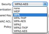
Security Settings
WEP – enable WEP encryption. WEP (Wired Equivalent Privacy) is based on the IEEE 802.11 standard and uses the RC4 encryption algorithm. Enabling WEP allows you to increase security by encrypting data being transferred over your wireless network. WEP is the oldest security algorithm, and there are few applications that can decrypt the WEP key in less than 10 minutes. WPA™/WPA2™ security methods should be used when possible.
WPA – enable WPA™ security mode. Wi-Fi Protected Access - WPA™ (IEEE 802.11i/D3.0) and WPA2™ (IEEE 802.11i) with pre-shared key management protocol offers improved security methods as they are new protocols that were created under the 802.11i standard to address weaknesses in the WEP approach.
WPA™ and WPA2™ support the following ciphers for data encryption:
TKIP - Temporal Key Integrity Protocol which uses RC4 encryption algorithm.
AES (also known as CCMP) - Counter Mode with Cipher Block Chaining Message Authentication Code Protocol which uses the Advanced Encryption Standard (AES) algorithm.
The device will use the strongest cipher (AES) in Station and Access Point wireless mode by default. If AES is not supported on the other side of the link the TKIP encryption will be used - like in situation when the device acts as Access Point with WPA security enabled and at least one wireless station (without AES support) is connected to it.
WPA – enable WPA™ security mode.
WPA-TKIP – enable WPA™ security mode with TKIP support only.
WPA-AES – enable WPA™ security mode with AES support only.
WPA2 – enable WPA2™ security mode.
WPA2-TKIP – enable WPA2™ security mode with TKIP support only.
WPA2-AES – enable WPA2™ security mode with AES support only.
WEP
WEP Security
WEP - Key Type and Key Index
Authentication Type: field relates only to the WEP security option. One of the following authentication modes should be selected if WEP security method is used:
Open Authentication – station is authenticated automatically by AP (selected by default).
Shared Authentication – station is authenticated after the challenge, generated by AP.
WEP Key Length: 64-bit (selected by default) or 128-bit WEP Key length should be selected if WEP security method is used. The 128-bit option will provide a bit higher level of wireless security.
Key Type: HEX (selected by default) or ASCII option specifies the character format for the WEP key if WEP security method is used.
WEP Key: WEP encryption key for the wireless traffic encryption and decryption should be specified if WEP security method is used:
For 64-bit – specify WEP key as 10 HEX (0-9, A-F or a-f) characters (e. g. AA) or 5 ASCII characters.
For 128-bit – specify WEP key as 26 HEX (0-9, A-F or a-f) characters (e. g. AABBCC) or 13 ASCII characters.
Key Index: allows to specify the Index of the WEP Key used. 4 different WEP keys can be configured at the same time, but only one is used. Effective key is set with a choice of 1, 2, 3 or 4.
WPA/WPA2
WPA - AES – enable WPA™ security mode with AES support only. Wi-Fi Protected Access - WPA™ (IEEE 802.11i/D3.0) with pre-shared key management protocol offers improved security methods as they are new protocols that were created under the 802.11i standard to address weaknesses in the WEP approach.
WPA2 - AES – enable WPA2™ security mode with AES support only. Wi-Fi Protected Access 2 - WPA2™ (IEEE 802.11i) with pre-shared key management protocol offers improved security methods as they are new protocols that were created under the 802.11i standard to address weaknesses in the WEP approach.
WPA Authentication
WPA/WPA2 PSK security
WPA Authentication: one of the following WPA™ key selection methods should be specified if WPA™ or WPA2™ security method is used:
PSK – WPA™ or WPA2™ with Pre-shared Key method (selected by default).
EAP – WPA™ or WPA2™ with EAP (Extensible Authentication Protocol) IEEE 802.1x authentication method. This method is commonly used in Enterprise networks. Note: AirOS v5.2 Web Management GUI supports only EAP-TTLS authentication method.
WPA Pre-shared Key: the pass phrase for WPA™ or WPA2™ security method should be specified if the Pre-shared Key method is selected. The pre-shared key is an alpha-numeric password between 8 and 63 characters long.
WPA/WPA2 EAP security (Station Mode)
EAP Authentication - Station Mode
WPA Identity: identification credential (also known as identity) used by the supplicant for EAP authentication (applicable to STA and STA WDS modes only).
WPA User Name: identification credential (also known as anonymous identity) used by the supplicant for EAP tunneled authentication (EAP-TTLS) in unencrypted form (applicable to STA and STA WDS modes only).
WPA User Password: password credential used by the supplicant for EAP authentication (applicable for STA and STA WDS modes only).
WPA/WPA2 EAP security (AP Mode)
EAP Authentication - AP Mode
Radius Server IP: specifies the RADIUS Server’s IP address. RADIUS is a networking protocol providing centralized Authentication, Authorization, and Accounting (AAA) management for computers in order to connect to, and use a network service.
Radius Server Port: specifies the RADIUS Server’s UDP port. The most commonly used port is 1812, but that depends on the RADIUS Server you are using.
Radius Server Secret: specifies the password. A shared secret is a case-sensitive text string used to validate communications between two RADIUS devices.
Note: When connecting devices in AP-WDS-to-AP-WDS mode, the WPA/WPA2 security methods will not function. When connecting AP-WDS devices to another AP-WDS device use none or the WEP security method. However, this may compromise the security of your network. In case of connecting STA-WDS clients to an AP-WDS device, all security methods are available and work properly.
MAC ACL
The maximum number of MAC ACL entries that can be managed trough the AirOS v5.2 Web GUI is 32 MAC addresses. In order to manage more than 32 entries, read this guide, which explains how to manage more MAC addresses modifying the configuration file.
MAC Address Control List
MAC ACL: MAC Access Control List (ACL) provides ability to allow or deny certain clients to connect to the AP (applicable to AP and AP WDS modes only).
MAC ACL can be enabled by selecting the Enabled checkbox.
There are two ways to set the Access Control List:
define certain wireless clients in the list which will have granted access to the Access Point while the access will be denied for all the remaining clients - MAC ACL Policy is set to Allow'.
define certain wireless clients in the list which will have denied access to the Access Point while the access will be granted for all the remaining clients - MAC ACL Policy is set to Deny.
The MAC addresses of the wireless clients can be added and removed to the list using the Add and Remove buttons.
Note: MAC Access Control is the weakest security approach. WPA™ or WPA2™ security methods should be used when possible.
Click Change button to save the changes.
[Content]
Network
AirOS v5.2 Network Page
The Network Page allows the administrator to setup bridge or routing functionality.
AirOS v5.2 powered devices can operate in bridge, router or SOHO router mode. The IP configuration as described below is required for device management purposes. IP addresses can either be retrieved from a DHCP server or configured manually. Use the Network menu to configure the IP settings.
AirOS Network Mode selection
Network Mode: specify the operating network mode for the device. There are three modes: bridge, router and SOHO router. The mode depends on the network topology requirements:
[Bridge] operating mode is selected by default as it is widely used by the subscriber stations, while connecting to Access Point or using WDS. In this mode, the device will act as a transparent bridge and will operate in Layer 2. There will be no network segmentation while broadcast domain will be the same. Bridge mode will not block any broadcast or multicast traffic. Additional Firewall settings can be configured for Layer 2 packet filtering and access control in Bridge mode.
[Router] operating mode can be configured in order to operate in Layer 3 to perform routing and enable network segmentation – wireless clients will be on different IP subnet. Router mode will block broadcasts while it is not transparent.
AirOS v5.2 supports Multicast packet pass-through in Router mode.
AirOS v5.2 powered Router can act as DHCP server and use Network Address Translation (Masquerading) feature, which is widely used by the Access Points. NAT will act as the firewall between LAN and WLAN networks. Additional Firewall settings can be configured for Layer 3 packet filtering and access control in Router mode.
[SOHO Router]: SOHO (= Small Office and Home Office) Router is basically a derivation from Router mode, which makes the LAN port become the WAN port, and the Wireless network (WLAN) become the local network.
In one-Ethernet-port devices (while operating in AP or AP-WDS) this mode works like the Router mode, except that the LAN port is labeled as “WAN port” and WLAN as LAN. In two-or-more-Ethernet-ports devices, the main Ethernet port becomes WAN, and WLAN and other LAN ports become the local network (LAN).
Disable Network
Disable Network: options can be used for disabling WLAN, LAN or WAN interface. This setting should be used with the exclusive care as no L2 or L3 connection can be established through the disabled interface. It will be impossible to access the AirOS based device from the wireless/wired network that is connected to the disabled interface. Disable WAN only applicable while operating in SOHO Router mode.
Network settings
Bridge Mode
Bridge mode Network Settings
In bridge mode the AirOS v5.2 based device forwards all the network management and data packets from one network interface to the other without any intelligent routing. For simple applications this provides an efficient and fully transparent network solution. WLAN (wireless) and LAN (Ethernet) interfaces belong to the same network segment which has the same IP address space. WLAN and LAN interfaces form the virtual bridge interface while acting as the bridge ports. The bridge has assigned IP settings for management purposes:
Bridge IP Address: The device can be set for static IP or can be set to obtain an IP address from the DHCP server it is connected to.
One of the IP assignment modes must be selected:
DHCP – choose this option to assign the dynamic IP address, Gateway and DNS address by the local DHCP server.
Static – choose this option to assign the static IP settings for the bridge interface.
IP Address: enter the IP address of the device while Static Bridge IP Address mode is selected. This IP will be used for the AirOS v5.2 device management purposes.
Bridge IP Address assigned manually (Static)
IP Address and Netmask settings should consist with the address space of the network segment where AirOS v5.2 device resides. If the device IP settings and administrator PC (which is connected to the device in wired or wireless way) IP settings will use different address space, the AirOS device will become unreachable.
IP Aliases
Netmask: This is a value which when expanded into binary provides a mapping to define which portions of IP address groups can be classified as host devices and network mask defines the address space of the network segment where AirOS device resides. 255.255.255.0 (or /24) Netmask is commonly used among many C Class IP networks.
Gateway IP: Typically, this is the IP address of the host router which provides the point of connection to the internet. This can be a DSL modem, Cable modem, or a WISP gateway router. AirOS v5.2 device will direct the packets of data to the gateway if the destination host is not within the local network.
Gateway IP address should be from the same address space (on the same network segment) as the AirOS device.
Primary/Secondary DNS IP: The Domain Name System (DNS) is an internet "phone book" which translates domain names to IP addresses. These fields identify the server IP addresses of where the AirOS device looks for the translation source.
Primary DNS server IP address should be specified for the device management purposes.
Secondary DNS server IP address is optional. It is used as the fail-over in case the primary DNS server will become unresponsive.
Bridge IP Address assigned automatically DHCP with IP fallback
DHCP Fallback IP: In case the Bridge is placed in Dynamic IP Address mode (DHCP) and is unable to obtain an IP address from a valid DHCP server, it will fall back to the static IP address listed here.
In case the IP settings of the AirOS v5.2 powered device are unknown, they can be retrieved with the help of the [UBNT_Discovery_Utility Ubiquiti Discovery Utility]. Multi-platform Utility should be started on the administrator PC which resides on the same network segment as the AirOS device.
AirOS v5.2 system will return to the default IP configuration (192.168.1.20/255.255.255.0) If the Reset to defaults routine is initiated.
DHCP Fallback Netmask: In case the Bridge is placed in Dynamic IP Address mode (DHCP) and unable to obtain an IP address from a valid DHCP server, it will fall back to the static Netmask listed here.
Spanning Tree Protocol: Multiple interconnected bridges create larger networks using the IEEE 802.1d Spanning Tree Protocol (STP), which is used for finding the shortest path within the network and to eliminate loops from the topology.
Spanning Tree Protocol enabled
If the STP is turned on, the AirOS Bridge will communicate with other network devices by sending and receiving Bridge Protocol Data Units (BPDU). STP should be turned off (selected by default) when the AirOS device is the only bridge on the LAN or when there are no loops in the topology as there is no sense for the bridge to participate in the Spanning Tree Protocol in this case.
Auto IP Aliasing configures automatically generated IP Address for the corresponding WLAN/LAN interface if enabled. Generated IP address is the unique Class B IP address from the 169.254.X. Y range (Netmask 255.255.0.0) which are intended for use within the same network segment only. Auto IP always starts with 169.254.X. Y while X and Y are last 2 digits from device MAC address (i. e. if the MAC is 00:15:6D:A3:04:FB, Generated unique Auto IP will be 169.254.4.251).
IP Aliases for internal and external network interface can be configured. IP Aliases can be specified using the IP Aliases configuration window which is opened while activating the "Configure" button.
IP Address is the alternative IP address for the LAN or WLAN interface, which can be used for the routing or device management purposes;
Netmask is the network address space identifier for the particular IP Alias;
Comments is the informal field for the comment of the particular IP Alias. Few words about the alias purpose are saved there usually;
Enabled flag enables or disables the particular IP Alias. All the added IP Aliases are saved in the system configuration file. However, only the enabled IP Aliases will be active during the AirOS system operation.
Newly added IP Aliases can be saved by activating Save button or discarded by activating Cancel button in the Aliases configuration window.
Firewall functionality on a bridge interface can be enabled using the "Enable Firewall" option. Bridge Firewall rules can be configured, enabled or disabled while using Firewall configuration window, which is opened with the "Configure" button.
Bridge mode Firewall Configuration Settings
Firewall entries can be specified by using the following criteria:
Interface the interface (WLAN or LAN) where filtering of the incoming/passing-through packets is processed;
IP Type sets which particular L3 protocol type (IP, ICMP, TCP, UDP) should be filtered;
Source IP/mask is the source IP of the packet (specified within the packet header), usually it is the IP of the host system which sends the packets;
Source Port is the source port of the TCP/UDP packet (specified within the packet header), usually it is the port of the host system application which sends the packets;
Destination IP/mask is the destination IP of the packet (specified within the packet header), usually it is the IP of the system which the packet is addressed to;
Destination Port is the destination port of the TCP/UDP packet (specified within the packet header), usually it is the port of the host system application which the packet is addressed to.
Comments is the informal field for the comment of the particular firewall entry. Few words about the particular firewall entry purpose are saved there usually.
On flag enables or disables the effect of the particular firewall entry. All the added firewall entries are saved in the system configuration file. However, only the enabled firewall entries will be active during the AirOS system operation.
Not operators can be used for inverting the Source IP/mask, Source Port, Destination IP/mask and Destination Port filtering criteria (i. e. if not is enabled for the specified Destination Port value 443, the filtering criteria will be applied to all the packets sent to any Destination Port except the 443 which is commonly used by HTTPS).
Newly added Firewall entries can be saved by activating Save button or discarded by activating Cancel button in the Firewall configuration window.
All the active firewall entries are stored in the FIREWALL chain of the ebtables filter table, while the device is operating in Bridge mode. Please refer to the ebtables manual for detailed description of the firewall functionality in Bridge mode.
The list can be updated using the Reload button.
Click Change button to save the changes made in the Network page.
Router Mode
Network - Router mode
The role of the LAN and WLAN interface will change accordingly to the Wireless Mode while the AirOS powered device is operating in Router mode:
- Wireless interface and all the wireless clients connected are considered as the internal LAN and the Ethernet interface is dedicated for the connection to the external network while the AirOS powered device is operating in AP/AP WDS wireless mode; Wireless interface and all the wireless clients connected is considered as the external network and all the network devices on LAN side as well as the Ethernet interface itself is considered as the internal network while the AirOS powered device is operating in Station/Station WDS mode.
Wireless/wired clients are routed from the internal network to the external one by work Address Translation (NAT) functionality works the same way.
WLAN Network Settings
IP Address: This is the IP addresses to be represented by the WLAN interface which is connected to the internal network according to the wireless operation mode described above. This IP will be used for the routing of the internal network (it will be the Gateway IP for all the devices connected on the internal network). This is the IP address can be used for the management purpose of the AirOS v5.2 powered device.
Netmask: This is used to define the device IP classification for the chosen IP address range. 255.255.255.0 is a typical netmask value for Class C networks, which support IP address range 192.0.0.x to 223.255.255.x. Class C network Netmask uses 24 bits to identify the network (alternative notation "/24") and 8 bits to identity the host.
Enable NAT and DHCP Server
Enable NAT: Network Address Translation (NAT) enables packets to be sent from the wired network (LAN) to the wireless interface IP address and then sub-routed to other client devices residing on its local network while the AirOS powered device is operating in AP/AP WDS wireless mode and in the contrariwise direction in "Station/Station WDS" mode.
Enable NAT Protocol: While NAT is enabled, data packets could be modified in order to allow pass-through to the Router. To avoid packets modification of some specific packets, like: SIP, PPTP, FTP, RTSP; uncheck the respective checkbox (-es).
NAT is implemented using the masquerade type firewall rules. NAT firewall entries are stored in the iptables nat table, while the device is operating in Router mode. Please refer to the iptables tutorial for detailed description of the NAT functionality in Router mode.
Static routes should be specified in order the packets should pass-through the AirOS v5.2 based device if the NAT is disabled in while operating in Router network mode.
Enable DHCP Server: Dynamic Host Configuration Protocol (DHCP) Server assigns IP addresses to clients who will be associate to the wireless interface while the AirOS powered device is operating in AP/AP WDS wireless mode and assigns IP addresses to clients who will connect to the LAN interface while the AirOS powered device is operating in Station/Station WDS mode.
DHCP Server range, Netmask and lease time
Range Start/End: This range determines the IP addresses given out by the DHCP server to client devices on the internal network which use dynamic IP configuration.
Netmask: This is used to define the device IP classification for the chosen IP address range. 255.255.255.0 is a typical netmask value for Class C networks, which support IP address range 192.0.0.x to 223.255.255.x. Class C network Netmask uses 24 bits to identify the network (alternative notation "/24") and 8 bits to identity the host.
Lease Time: The IP addresses given out by the DHCP server will only be valid for the duration specified by the lease time. Increasing the time ensure client operation without interrupt, but could introduce potential conflicts. Lowering the lease time will avoid potential address conflicts, but might cause more slight interruptions to the client while it will acquire new IP addresses from the DHCP server. The time is expressed in seconds.
DNS Proxy and Port Forwarding settings
Enable DNS Proxy: The DNS Proxy forwards the Domain Name System requests from the hosts which reside in the internal network to the DNS server while AirOS powered device is in operating in Router mode. Valid Primary DNS Server IP needs to be specified for DNS Proxy functionality. Internal network interface IP of the AirOS powered device should be specified as the DNS server in the host configuration in order DNS Proxy should be able to get the DNS requests and translate domain names to IP addresses afterwards.
Port Forwarding: Port forwarding allows specific ports of the hosts residing in the internal network to be forwarded to the external network. This is useful for a number of applications such as FTP servers, gaming, etc. where different host systems need to be seen using a single common IP address/port.
Port Forwarding example
Port Forwarding rules can be set in Port Forwarding window, which is opened by enabling the Port Forwarding option and activating the Configure button.
Port Forwarding entries can be specified by using the following criteria:
Private IP is the IP of the host which is connected to the internal network and needs to be accessible from the external network;
Private Port is the TCP/UDP port of the application running on the host which is connected to the internal network. The specified port will be accessible from the external network;
Type is the L3 protocol (IP) type which needs to be forwarded from the internal network.
Public Port is the TCP/UDP port of the AirOS v5.2 based device which will accept and forward the connections from the external network to the host connected to the internal network.
Comments is the informal field for the comment of the particular port forwarding entry. Few words about the particular port forwarding entry purpose are saved there usually.
Enabled flag enables or disables the effect of the particular port forwarding entry. All the added firewall entries are saved in the system configuration file. However, only the enabled port forwarding entries will be active during the AirOS system operation.
Newly added port forwarding entries can be saved by activating Save button or discarded by activating Cancel button in the Port Forwarding configuration window.
Auto IP Aliasing configures automatically generated IP Address for the corresponding WLAN/LAN interface if enabled. Generated IP address is the unique Class B IP address from the 169.254.X. Y range (Netmask 255.255.0.0) which are intended for use within the same network segment only. Auto IP always starts with 169.254.X. Y while X and Y are last 2 digits from device MAC address (i. e. if the MAC is 00:15:6D:A3:04:FB, Generated unique Auto IP will be 169.254.4.251).
IP Aliases
IP Aliases for internal and external network interface can be configured. IP Aliases can be specified using the IP Aliases configuration window which is opened while activating the "Configure" button.
IP Address is the alternative IP address for the LAN or WLAN interface, which can be used for the routing or device management purposes;
Netmask is the network address space identifier for the particular IP Alias;
Comments is the informal field for the comment of the particular IP Alias. Few words about the alias purpose are saved there usually;
Enabled flag enables or disables the particular IP Alias. All the added IP Aliases are saved in the system configuration file. However, only the enabled IP Aliases will be active during the AirOS system operation.
Newly added IP Aliases can be saved by activating Save button or discarded by activating Cancel button in the Aliases configuration window.
LAN Network Settings
LAN IP Address: This is the IP addresses to be represented by the LAN or WLAN interface which is connected to the external network according to the wireless operation mode described above. This is the IP address can be used for the routing and the device management purposes.
The external network interface can be set for static IP or can be set to obtain an IP address from the DHCP server which should reside in the external network. One of the IP assignment modes must be selected for the external network interface:
DHCP – choose this option to obtain the IP address, Gateway and DNS address dynamically from the external DHCP server.
PPPoE – choose this option to obtain the IP address, Gateway and DNS address dynamically from the external PPPoE server.
Static – choose this option to assign the static IP settings for the external interface.
LAN IP Address assigned manually - Static
IP Address and Netmask settings should consist with the address space of the network segment where AirOS device resides. If the device IP settings and administrator PC (which is connected to the device in wired or wireless way) IP settings will use different address space, the AirOS device will become unreachable. (Applicable for Static mode only)
Netmask: This is used to define the device IP classification for the chosen IP address range. 255.255.255.0 is a typical netmask value for Class C networks, which support IP address range 192.0.0.x to 223.255.255.x. Class C network Netmask uses 24 bits to identify the network (alternative notation "/24") and 8 bits to identity the host. (Applicable for Static mode only)
Gateway IP: is the IP address of the host router which resides on the external network and provides the point of connection to the next hop towards the internet. This can be a DSL modem, Cable modem, or a WISP gateway router. AirOS device will direct all the packets to the gateway if the destination host is not within the local network. (Applicable for Static mode only)
Gateway IP address should be from the same address space (on the same network segment) as the AirOS device's external network interface (Wireless interface in the Station case and the LAN interface in the AP case). (Applicable for Static mode only)

|
Из за большого объема этот материал размещен на нескольких страницах:
1 2 3 4 |
