

Партнерка на США и Канаду по недвижимости, выплаты в крипто
- 30% recurring commission
- Выплаты в USDT
- Вывод каждую неделю
- Комиссия до 5 лет за каждого referral
Manual of Newlydraw1
1 Interface operation
Inferface Components
The follwing picture is the initial screen of the program.
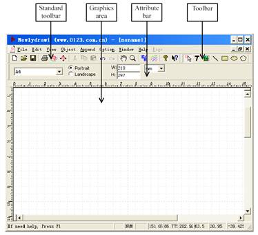
Most functions of the program can be found in the menu bar, tool bar and attribute bar. The functions only use the keyboard can be introduced in the following sections.
The tool icon name is displayed when the pointing device moves over the tool icon. Predefined layout is displayed when the pointing device moves over “A4” pull-down box.
The property bar can be changed to another mode according to your selection.
Predefined layout: You can select a predefined layout in the pull-down box and the width and height of the layout is changed to specified dimension. You can input the width and height directly if you select “user” in the pull-down box.
Orientation: This software offers portrait and landscape for changing the layout orientation.
Width, Height: The width and height of current layout.
Length measurement units: Such as mm, point and inch. If you change the measurement units, the value of width and height will be changed at same time.
2 Import
This program can import DXF, PLT, BMP, JPG files.
Click the import button  from the toolbar or choose Import from File menu. The file selction dialog box displays.
Select a file to import.
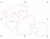
Handles: There are eight handles on the object.
Modification: By holding down the pick button on the pointing device and drag the mouse, you can modify the size of this object. And you can press trl if you do not change the scale between the width and height.
Combined objects attribute bar:

Center coordinates: The coordinates of the center of the combined object. They can be modified.
Dimension: The width and height of the combined object. They can be modified.
Engrave mode: cut.
3 Drawing
a. Line
Drawing: Click the line icon  on the toolbar and hold down the pick button on the pointing device at the first point of the line and drag to the second point of the line, then release the pick button.
As the following picture:
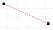
Handles: The black dot on the endpoint of the line. The objects you selected have handles and different objects have different handles.
Note: If you press “Ctrl” on the keyboard during drawing the line, you’ll get a horizontal or vertical or 45°line.
Modification: The pointing device moves on the handle and the cursor changes to another holding down the pick button on the pointing device, you can modify the position of the endpoint.
Move the line by using mouse: The mouse moves on the object you want to move and the cursor changes to another holding down the pick button on the pointing device, you can move the object to a new position.
Move the line by using keyboard: Select object you want to move then press the direction key on the keyboard, the object moves 1 millimeter each time. If you press “Ctrl” at same time, the object moves 0.1 millimeters each time.
Cancel selection: Move the mouse to a blank space in the graphic area and click; The handles disappear and the property bar changes to the form of the chapter 1.
Selection: The mouse move over the object you want to select and color of the object will be changed. When the color is changed click left button of the mouse and the handles of the selected object appear and the property bar changes to the line attribute bar.
Line attribute bar:
Choose from the toolbar or just finished a line or choose a line on the graphics area, the attribute bar will be changed into line attribute bar. Refer to the following picture.

Center coordinates: The coordinates of line’s center. They can be modified.
Length of line: The length of line on the horizontal direction and on the vertical direction. They can be modified.
Engrave mode: Scan or cut.
b. Rectangle (square)
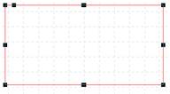
Drawing: Click the line icon  on the toolbar and hold down the pick button on the pointing device at the first point of the rectangle and drag to finish the rectangle, then release the pick button.
As the following picture:
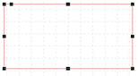
Handles: There are nine black dot on the rectangle. It means the rectangle has been selected.
Note: If you press trl on the keyboard during drawing the rectangle, you ‘ll get a square.
Modification 1: The mouse moves on the object you want to move and the cursor changes to another holding down the pick button on the pointing device, you can move the object to a new position. If you want to modify the size of the rectangle, you can hold down the pick button on the pointing device when the mouse moves on the handles and the cursor changes to another form.
Modification 2: The mouse moves on the handle (as the following picture) and the cursor changes to another holding down the pick button on the pointing device, you can fillet the rectangle. If you press “Ctrl” on the keyboard during modification, you ll get a fillet with the same size on horizontal and vertical direction.

|
Rectangle attribute bar:
Choose  from the toolbar or just finished a rectangle or choose a rectangle on the graphics area, the attribute bar will be changed into rectangle attribute bar. Refer to the following picture.

Center coordinates: The coordinates of rectangles center. They can be modified.
Dimension: The width and height of the rectangle. They can be modified.
Engrave mode: Scan or cut.
Corner shape: You can choose different corner shapes of the rectangle.
Corner size: If the corner is a fillet, X is the corner horizontal radius and Y is the corner vertical radius.
A rectangle and its corners are not right-angled.
1. Draw a rectangle at first.
2. Select a kind of shape listed in the corner shape on the attribute bar.
3. Set the corner radius or use the method of modification 2.
c. Ellipse (circle), arc
Drawing: Click the line icon  on the toolbar and hold down the pick button on the pointing device at the first point of a rectangle tangent to the ellipse and drag to finish the ellipse or circle, then release the pick button.
As the following picture:
|
 .
. 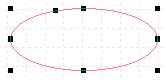
Handles: There are nine black dot on the ellipse. It means the rectangle has been selected.
Note: If you press trl on the keyboard during drawing the ellipse, you’ll get a circle.
Modification 1: The mouse moves on the rectangle tangent to the ellipse or circle you want to modify and the cursor changes to another holding down the pick button on the pointing device, you can modify the size of ellipse. And you can press “Ctrl” if you want to get a circle.
Modification 2: The mouse moves on the handle (as the following picture ) and the cursor changes to another holding down the pick button on the pointing device, you can get an arc or a pie. If you drag the handle outside of ellipse, you will get an arc. If you drag the handle inside of ellipse, you will get a pie.
Ellipse attribute bar:
Choose  from the toolbar or just finished a ellipse or choose a ellipse on the graphics area, the attribute bar will be changed into ellipse attribute bar. Refer to the following picture.

Center coordinates: The coordinates of ellipses center. They can be modified.
Dimension: The width and height of the ellipse. They can be modified.
Engrave mode: Scan or cut.
d. Polygon, star
Drawing: Click the icon  on the toolbar and hold down the pick button on the pointing device at the first point of a rectangle tangent to the polygon or star and drag to finish the polygon or star, then release the pick button.
As the following picture:
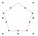
Handles: The handles are on the endpoints and midpoints of every edge of polygon and in addition the rectangle has eight handles. It means the polygon has been selected.
Note 1: If you press trl on the keyboard during drawing the polygon, you’ll get a regular polygon.
Modification 1: the mouse moves on the rectangle tangent to the polygon you want to modify and the cursor changes to another holding down the pick button on the pointing device, you can modify the size of polygon. And you can press “Ctrl” if you want to get a regular polygon.
Modification 2: the mouse moves on the endpoint or midpoint of the edge of polygon and the cursor changes to another holding down the pick button on the pointing device, you can modify the position of the endpoint or the shape of the edge.
Note 2: If you press trl on the keyboard when you move the endpoint of polygon, the azimuth angle of the endpoint will not be changed.
Polygon attribute bar:
Choose from the toolbar or just finished a polygon or choose a polygon on the graphics area, the attribute bar will be changed into polygon attribute bar. Refer to the following picture.

Center coordinates: The coordinates of the center of the rectangle tangent to the polygon or star. They can be modified.
Dimension: The width and height of the rectangle tangent to the polygon or star. They can be modified.
Engrave mode: Scan or cut.
Star: If you choose this option, you can get a star not a polygon.
Vertexes: The number of vertexes of the polygon.
4 Text
a. Flexible text
Flexible text means the size of text can be changed synchronous with the textbox. Choose the Text button  from the toolbar, and click in the graphics area, then appear a textbox (refer to the following picture), you can edit text and click the Enter key when you finish the edition.

Note: Flexible Text can not wrap line automatically. If you want to edit several rows, you can use <Ctrl+Enter> to edit the next row.
b. Paragraph text
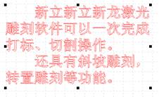
Paragraph text can wrap line automatically and you can use <Ctrl+Enter> to edit the next paragraph. The size of text and textbox can be modified independently.
Choose the Text button from the toolbar, and hold down the pick button on the pointing device in the graphics area, then appear a textbox (refer to the following picture), you can edit text and click the Enter key when you finish the edition.
c. Text attribute bar
Choose from the toolbar, the attribute bar will be changed into text attribute bar. Refer to the following picture.

Center coordinates: The coordinates of the center of the text. They can be modified.
Dimension: The width and height of the text. They can be modified.
Engrave mode: Scan or cut.
d. Finish the text operating
Click the icon  and the text operating will be terminated.
5 Edit object
a. Selection tool
Choose the selection button from the toolbar to select the object. You can use this tool to select, move or modify the shape and size of the object.
If you want to edit an object, you must select the object at first.
Pick
Use the selection tool and click on the objects you want to select.
1. Click the icon from toolbar.
2. The mouse move over the object you want to select and color of the object will be changed. When the color is changed click left button of the mouse
3. If you want to select several objects after pick one, press the Shift in the keyboard, repeat the second step in the same time. Select other objects in turn.
4. If you want to take out some object, press the Shift in the keyboard, select the object in the same time.
Window
1. Click the icon from toolbar.
2. Hold down the pick button on the pointing device at the first point and release the pick button until all the objects you want to select are in this window.
Choose “Select All” from Edit menu. You can select all the objects in the graphics area.
b. Move
Move an object by using mouse:
1. Select the object you want to move.
2. The mouse moves on the object and the cursor changes to another holding down the pick button on the pointing device and drag, you can move the object to a new position.
Move an object by using keyboard:
1. Select the object you want to move.
2. Press the direction key on the keyboard, the object moves 1 millimeter each time.
3. If you press trl at same time, the object moves 0.1 millimeters each time.
Move an object accurately
1. Select the object you want to move.
2. In attribute bar,”X” is X-coordinate of the center of the object, “Y” is Y-coordinate of the center of the object. You can modify the coordinates directly, then press “enter” button on the keyboard. The object will be moved to the specified position.
c. Modify the dimension and shape of an object
Modify an object by using mouse
1. Select the object you want to modify.
2. The mouse moves on the handle of the object and the cursor changes to another holding down the pick button on the pointing device and drag, you can modify the dimension and shape of the object.
Setting the dimension and shape of an object.
1. Select the object you want to modify.
2. You can modify the parameters directly in attribute bar, then press “enter” button on the keyboard.
d. Split, combine and translate
You can split an combined object to several single objects and you can also combine several single objects or translate text to a combined drawing.
Split
1. Select the combined object you want to split.
2. Click “Split” on attribute bar.
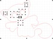
Combine
1. Select the objects you want to combine.
2. Click “Combine” on attribute bar.
Translate
1. Select a text block.
2. Click “To cur” on attribute bar and the text block is translated to a combined object.
Note: If the text block has been transformed to a combined object, the content of the text would not be modified.
e. Copy and paste
1. Select the objects to copy.
2. Click  on the standard toolbar to copy objects to the clipboard.
3. Click  on the standard toolbar to paste objects from the clipboard.
You can also use Copy in the Edit menu or <Ctrl+C> to copy objects.
You can also use Paste in the Edit menu or <Ctrl+V> to paste objects.
Matrix copy
Creates an array defined by a number of rows and columns of the selected objects.
1. Select the object to copy.
2. Choose “Matrix copy” from Edit menu. The dialog box is as follows:
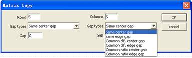
Rows: The rows of objects you can get after copied.
columns: The number of columns.
Gap: The distance between rows and the distance between columns.
Gap types: In the pull-down list:
Same center gap, Same edge gap: All distance between centers and gap between nearest sides are th e same.
Common dif. center gap, Common dif. edge gap: The next distance is greate than last by a common difference.
Common dif. center gap, Common dif. edge gap: The next distance is greater(smaller) than the last by a common difference.
Common ratio center gap, Common ratio edge gap: The next distance is greater(smaller) than last by a common ratio.
3. Click “OK” after the parameters specified.
f. Cut and delete
Delete
You can cut objects to the clipboard.
1. Select the objects to cut.
2. Click  on the standard toolbar.
You can also use Cut in the Edit menu or <Ctrl+X> to cut objects.
Delete
Delete objects from graphics area.
1. Select the object to delete.
2. Click Delete on the keyboard or select Delete from Edit menu.
g. Undo and redo
You can choose  from the standard toolbar to undo the most recent action and you can also choose
  from the standard toolbar to redo an action.
6 Cutting management
a. Cut order
If you did not adjust the cut order, cut the drawings orderly according to the creating order.
Modify the cutting order: Choose  from toolbar or choose the Cut order from Object menu.
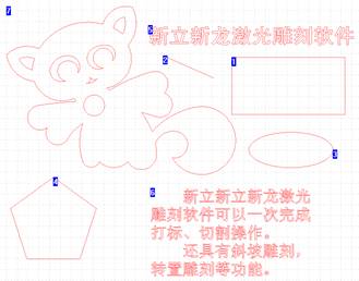
Modify the cut order from No. one: Click on the first object for cutting and this one will be cut firstly; click on the second object for cutting and this one will be cut secondly. The rest may be deduced by analogy.
Change the cut order from a number: If from one to three the order is right and you want to modify the cut order from No. 4, you can press Ctrl on the keyboard and at the same time click the last right number 3,then click the next number in order until the cut order is right.
Finish the modification: Click on the blank in the graphics area to finish the modification.
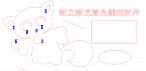
The cut order of the combined object.
Simple object: The object is composed of single linetype. Such as line, circle etc.
Combined object: The object is composed of several independent sub-path. Such as the DXF files.
The cut order of the combined object: the cut order of sub-path.
Modify the cut order of the combined object: Firstly select the combined object. Then choose  from the toolbar or choose cut order from the Object menu. The following steps are the same as the method above.
7 Engrave
Steps
1. Select the objects to engrave.
2. Click engrave button  on the toolbar.
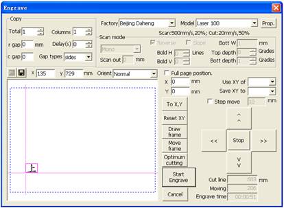
3. Click Start engrave.
Position
Stop: Click this button the machine will stop.
Step move: You can select Step move and specify the distance to move; when you click the direction key, the machine will move the specified distance then stop. If you press the direction key when Step move is not selected, the machine will move until you release this button.
Repeat engrave(Copy)
Total: The amount of repeat engraving.
Columns: The number of columns.
r gap: The distance between rows. If the distance is a negative number, it means that the order of engraving is from the bottom up.
c gap: The distance between columns If the distance is a positive number, it means that the order of engraving is from left to right.
Gap types: In the pull-down list, it contains distance between Centers and gap between nearest Sides.
Delay: The delay time between each engrave in repeat engraving.
Note: These parameters will be memorized in the program.
Start engrave
If the parameters and position of engraving have been specified, you can click Start engrave on the dialog box to cut the objects selected.
8 Save and open
Newlydraw files (*.ndr): All drawings on the current layout can be saved in hardware. This file is named as graphics file.
Save: Click the  on the toolbar or choose Save from the file menu. If the drawing is named, the drawing can be saved without requesting a file name. If the drawing is unnamed, the Save As dialog box will flyout and the drawing can be saved under the file name you specify.
If the drawing is read-only, select the save as to save the changed file under a different name.
Open: From the File menu, choose Open, Or from the toolbar, choose  . In the Open dialog box, double-click the file name in the list of files. You can also open the drawing by entering the drawing name and choosing OK.
New: From the file menu, choose New. Or choose  from the toolbar,
