
Партнерка на США и Канаду по недвижимости, выплаты в крипто
- 30% recurring commission
- Выплаты в USDT
- Вывод каждую неделю
- Комиссия до 5 лет за каждого referral
УСТОЙЧИВОСТЬ ГАЗОВОГО ПОТОКА НА СПИНКЕ ПРОФИЛЯ ЛОПАТКИ
, ,
«Сатурн», г. Рыбинск, Россия.
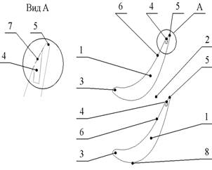
В настоящей работе предлагается на этапе проектирования лопатки газовой турбины рассчитать и ввести в конструкцию геометрию среза профиля пера лопатки, расположенного на участке от отверстий для выпуска охлаждающей среды до выходной кромки таким образом, чтобы участок среза был с переменной площадью проходного сечения, увеличивающейся к выходной кромке. Такая геометрия среза позволяет вернуть горло лопатки на выходную кромку, что приводит к большей гидродинамической устойчивости потока газа.
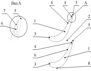
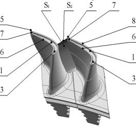
Кроме того, в ходе работы получено, что изменение формы выходной кромки - ее подрезка или наращивание по отношению к исходной - приводит к возникновению условий для изменения перепада давления по системе охлаждения рабочей лопатки. Газ, протекающий в межлопаточном канале 2, имеет наибольшее давление в сечении горла в начале среза S1 , перед отверстиями 4, и наименьшее давление на срезе от S1 до S2 , что способствует большему перепаду давления для выдува охлаждающего воздуха. При таком выполнении лопатки 1 давление на спинке 8 в области выходной кромки 5 минимальное, что улучшает выход охлаждающей среды из отверстия 4.
Организация выдува необходимого количества охлаждающего воздуха в выходную кромку при допустимом увеличении потерь кинетической энергии возможна при изменении выходной кромки в интервале aвых кр/aг ≈1±2%, где aг - минимальное расстояние от спинки до корыта (горло лопатки), aвых кр – минимальное расстояние от спинки лопатки до модифицированной, что подтверждается аналогичными исследованиями и на лопатках других турбин.
При реализации настоящей модификации получается так называемое плавающее горло. Это участок межлопаточного канала от начала скоса до выходной кромки с постоянной геометрической площадью на входе и на выходе, включающий в себя выдув охлаждающего воздуха. Несмотря на геометрическое равенство физическое горло окажется на выходной кромке из-за притока охлаждающего воздуха. Выдув в скос позволяет вернуть горло на выходную кромку. Получаем расчетную пропускную способность турбины.
Численные исследования проведены на примере рабочей лопатки 1-ой ступени ТВД двигателя Е70/8РД. В ходе работы в ANSYS CFX 14.0 была решена задача вязкого обтекания лопатки с постоянным по высоте сечением (поочередно корневым, средним и периферийным). Расчетные модели выполнены в программном комплексе для построения неструктурированных сеток ANSYS ICEM CFD 11.0. Для расчетов использовалась модель турбулентности SST. Качество математических моделей соответствует всем общеизвестным требованиям: высота первой ячейки составляет 1·10‑5 м, соотношение размеров между рядом стоящими ячейками не превышает 3.4, стыкуемые ячейки совпадают, угол элемента не меньше 14º.
По результатам работы получено, что модификация выходной кромки в рекомендуемых пределах приводит к повышению экономичности и эффективности охлаждения, в частности снижения расхода охлаждающего воздуха на 0,4 %. На данную разработку оформлен патент.
Литература
1. , , Шуверова свидетельство Российской федерации №1 кл. F01D5/08, 1996.
GAS FLOW STABILITY ON SUCTION SIDE OF THE PROFILE
OF THE BLADE
E. Kolesova, I. Nemtyreva, F. Karpov
OAO NPO Saturn, Rybinsk, Russia
In this work one of the ways to increase the cooling air flow through the blade gas turbine cooling system at the cooling air blowing out to the pressure surface in front of the trailing edge at the expense of the edge shape modification is considered. While trimming the trailing edge the blade ring throat section is transferred to the section in front of the cooling air outlet holes. Such geometry of the cut allows to return the throat of the blade on output edge that brings about hydrodynamic of stability of the flow of the gas.
In the presented work at the blade design stage the geometry of the section is calculated, the section being located within the zone of the holes for cooling medium outlet and the blade trailing edge in such a way as the section area have a variable flow area increasing to the trailing edge. This geometry of the section does not concern the theoretical profile of the blade airfoil, and therefore has no impact on the flow about the airfoil.
In the course of work it was found that a change of the trailing edge shape, i. e. its cutting or buildup relative to the initial shape, results in creation of conditions for changing the pressure differential from S1 to S2 within the blade cooling system. Under such performing the blade 1 pressure on back 8 in the field of output edge 5 minimum that perfects output cooling air from hole 4.
Organization of the required quantity of the cooling air blowout to the trailing edge at the allowable increase of the kinetic energy losses is possible with the trailing edge modification within the range of atrail. edge/ath ≈1±2%, where ath is the minimum distance from the suction surface to the pressure surface of the blade (blade throat), atrail. edge is the minimum distance from the blade suction surface to the modified edge, which is confirmed by the similar investigations and on blades of other turbines.
At realization persisting modification is got floating blade throat. This area blade channel from begin rake before output edge with constant geometric area at the input and on output, including in itself invented coolling air. In spite of geometric equality physical throat will turn out to be on output edge because of influx coolling air. We get the calculation gas flow of the gas through turbine.
The numerical investigations were conducted on HPT Stage 1 blade of the Е70/8РД engine and product 30. Through application of ANSYS CFX 14.0 the task of viscous flow about the airfoil with a section constant in height (successively root, middle and tip) was solved. The calculated models are made in ANSYS ICEM CFD 11.0 software system for unstructured grids generation. For calculations the SST turbulence model was used. Quality of the mathematical models corresponds to all requirements. Height of the first cell forms 1·10‑5 m, jointing cell coincide, the corner of the element not less 14º.
Based on the results of work it was found that modification of the trailing edge within the recommended limits results in increase of the performance and cooling efficiency, particularly reduction of the cooling air flow by 0,4 %. The patent has been filed for this development.
Literature
1. A. Ageev, G. Nagoga, T. Suverova. Certificate of authorship RU №1 кл. F01D5/08, 1996.
