Партнерка на США и Канаду по недвижимости, выплаты в крипто
- 30% recurring commission
- Выплаты в USDT
- Вывод каждую неделю
- Комиссия до 5 лет за каждого referral

PREMIER SENSOR – OPERATIONAL GUIDELINES
|

|
PREMIER SENSOR – OPERATIONAL GUIDELINES
PREMIER SENSOR – OPERATIONAL GUIDELINES
PRINCIPLE OF OPERATION
PELLISTOR REPLACEMENT
SELECTING POSITIVE OR NEGATIVE VERSIONS
“VOLTAGE” OUTPUT VERSION
USING THE DIGITAL OUTPUT
TEMPERATURE PERFORMANCE
TEMPERATURE PERFORMANCE
LINEARITY PERFORMANCE
RELATIVE RESPONSES
APPLYING A LINEAR CROSS-REFERENCE FACTOR
METHANE SENSOR – RELATIVE RESPONSES
POWER SUPPLY LIMITS
TEMPERATURE LIMITS
RESOLUTION
SENSOR WARM-UP TIME
OVERRANGE CONDITION
POSITIVE AND NEGATIVE SUPPRESSION
FAULT INDICATION
FLOW RATE CONSIDERATIONS
HANDLING PRECAUTIONS

Typical hydrocarbon absorption spectrum
PRINCIPLE OF OPERATION
Typical hydrocarbon absorption spectrum |
Energy from the pulsed source travels through the gas sample chamber of the sensor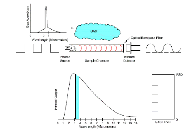




NO GAS PRESENT IN THE SENSOR
1) With no gas present, the infrared lamp is pulsed on and off, the energy passes through the gas chamber to the pyroelectric detector. The detector generates two signals, an active channel that responds to the target gas, and a reference channel that is not affected by gas. The bandpass filter on the active channel only allows energy at the wavelength of absorption of the target gas into the detector. This is the zero gas condition.
The ratio of the active channel signal to the reference signal is stored as the “Zero” value.




GAS ENTERS THE SENSOR
2) As gas enters the sensor, some of the infrared energy that is entering the detector through the bandpass filter is absorbed by the gas. This causes the active signal to be reduced in amplitude. The calculated gas concentration increases from zero.




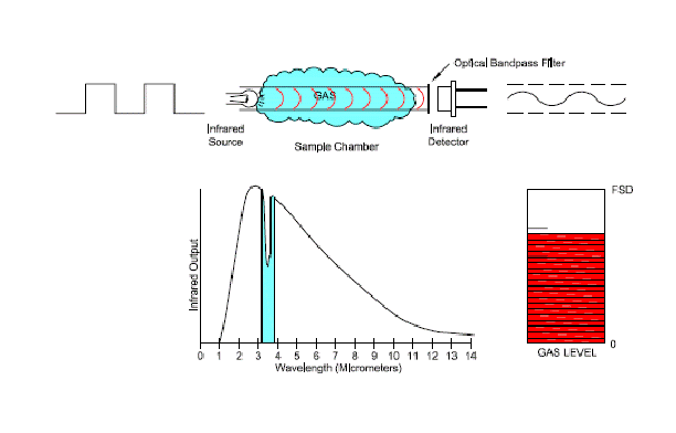
GAS COMPLETELY FILLS THE SENSOR
3) Gas has now completely occupies the sample chamber of the sensor. The gas concentration is calculated by using the relationship between the signal sizes with, and without gas present.
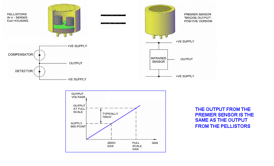 PELLISTOR REPLACEMENT
|
SELECTING POSITIVE OR NEGATIVE VERSIONS
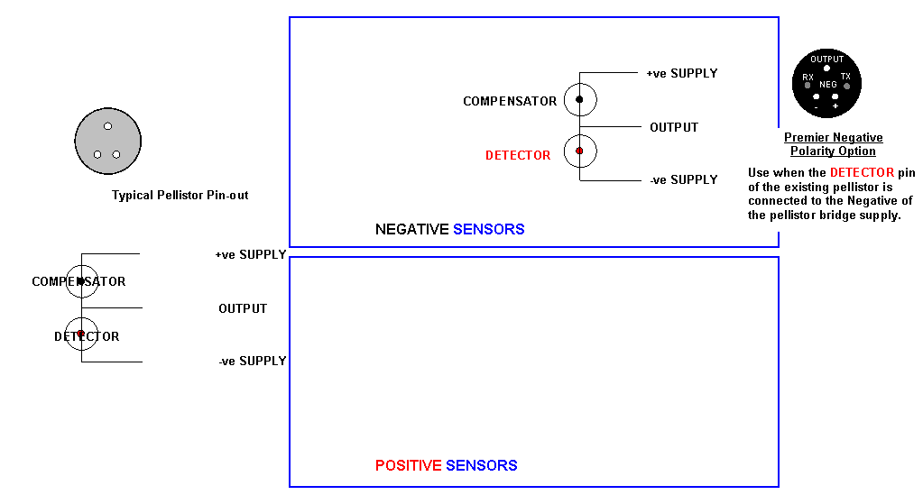
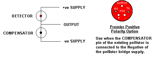
|
“VOLTAGE” OUTPUT VERSION
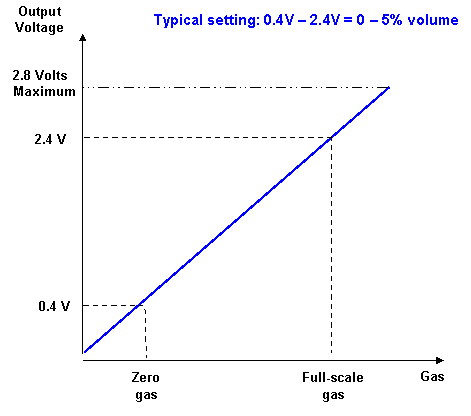 |

THE OUTPUT VOLTAGE RANGE CAN BE SPECIFIED ANYWHERE
BETWEEN 0V AND 2.8V FOR ZERO GAS TO FULL-SCALE GAS
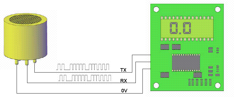
USING THE DIGITAL OUTPUT
 | |||
|
| ||
|
TEMPERATURE PERFORMANCE
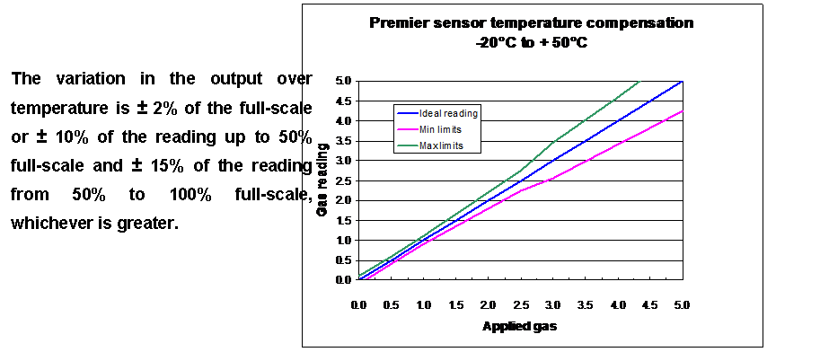 |
THE PERFORMANCE SHOWN ABOVE APPLIES TO ALL SENSORS
LINEARITY PERFORMANCE
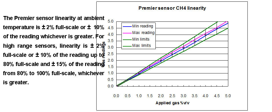
THE PERFORMANCE SHOWN BY THE GRAPH APPLIES TO ALL SENSORS, EXCEPT THE HIGH RANGE VERSIONS
RELATIVE RESPONSES
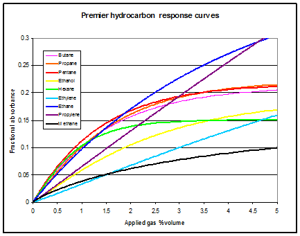
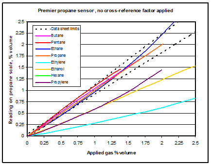
BASIC RESPONSE WITHOUT ANY LINEARISATION RELATIVE RESPONSE OF A PROPANE SENSOR
APPLYING A LINEAR CROSS-REFERENCE FACTOR
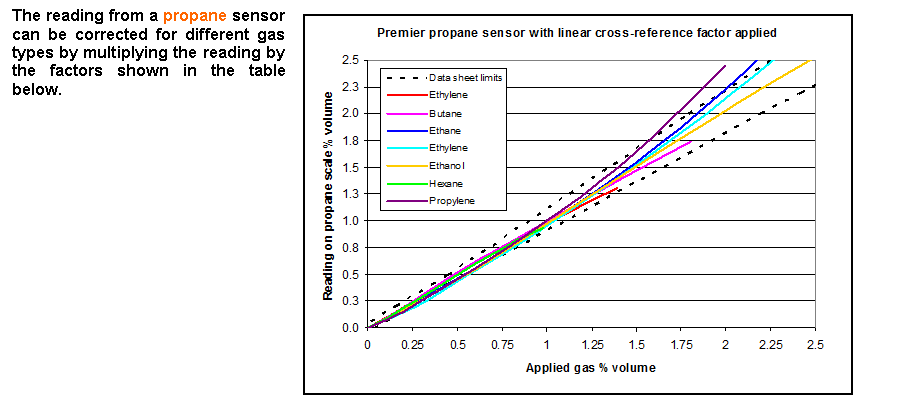 |
GAS | Multiplication factor |
Butane | 0.97 |
Pentane | 0.89 |
Hexane | 0.80 |
Ethanol | 1.65 |
Ethylene | 3.43 |
Propylene | 1.69 |
Ethane | 1.01 |
RESPONSE OF A PROPANE SENSOR WITH LINEAR
CROSS-REFERENCE FACTORS APPLIED
METHANE SENSOR – RELATIVE RESPONSES
This graph demonstrates that a methane sensor is only useful for measuring methane. The response to the other gasses shown is very different to methane, therefore a cross-reference factor cannot be used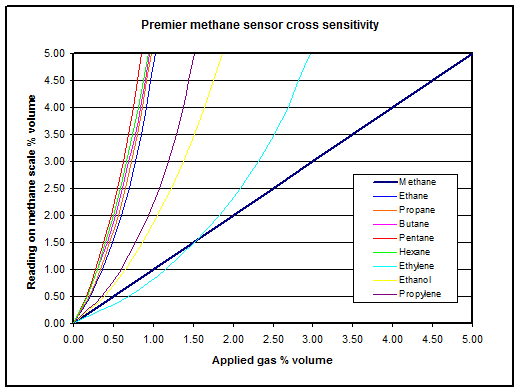
RELATIVE RESPONSE OF A METHANE SENSOR
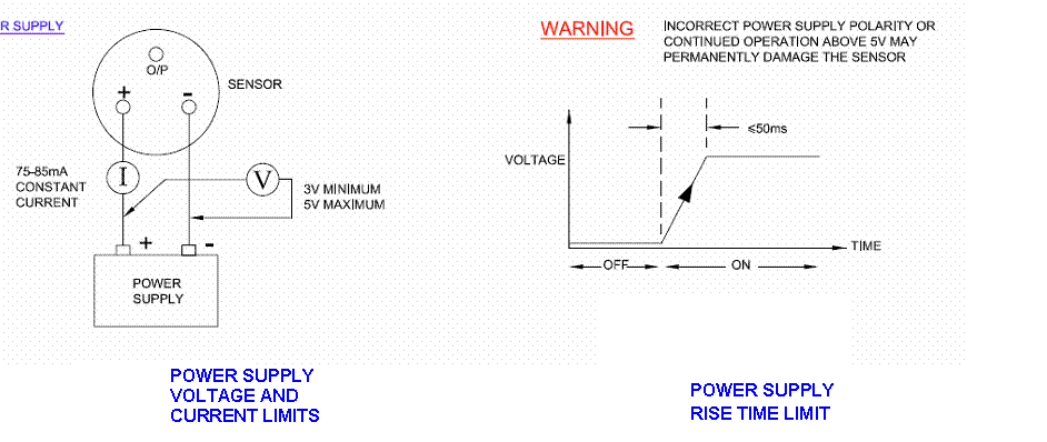
POWER SUPPLY LIMITS
OPERATING TEMPERATURE LIMITS
TEMPERATURE TRANSIENT LIMITS
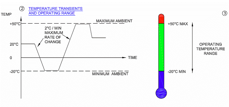 TEMPERATURE LIMITS
OPERATING TEMPERATURE LIMITS |
TEMPERATURE TRANSIENT LIMITS |
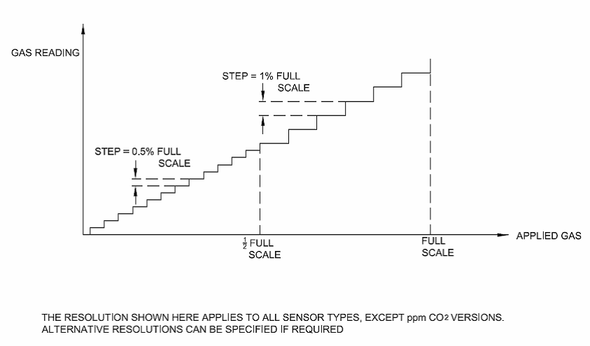 RESOLUTION
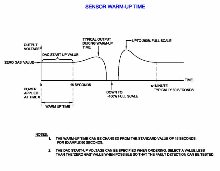
SENSOR WARM-UP TIME


OVERRANGE CONDITION
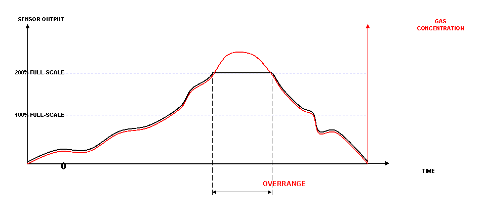

NOTE: THE ACCURACY OF THE OUTPUT IS ONLY GUARANTEED UP TO 100% FULL-SCALE OF THE SENSOR
POSITIVE AND NEGATIVE SUPPRESSION
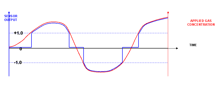

GRAPH SHOWING THE EFFECT OF APPLYING POSITIVE AND NEGATIVE SUPPRESSION VALUES OR +1.0 AND -1.0
THE CALCULATED GAS VALUE IS NOT TRANSFERRED TO THE OUTPUT UNTIL THE GAS LEVEL EXCEEDS EITHER +1.0 OR – 1.0
OTHER VALUES FOR SUPPRESSION CAN BE USED, AND NEED SPECIFYING WHEN ORDERING THE SENSOR.
“BRIDGE” OUTPUT SENSORS
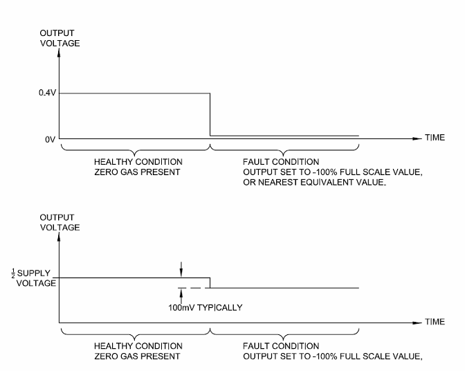
“VOLTAGE” OUTPUT SENSORS
0.4V = ZERO GAS
2.4V = FULL-SCALE GAS
FAULT INDICATION
“BRIDGE” OUTPUT SENSORS
|
“VOLTAGE” OUTPUT SENSORS
0.4V = ZERO GAS 2.4V = FULL-SCALE GAS |
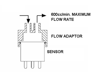
FLOW RATE CONSIDERATIONS
 | |
|
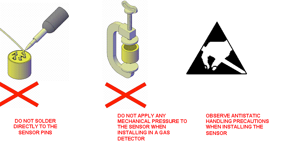
HANDLING PRECAUTIONS