
Партнерка на США и Канаду по недвижимости, выплаты в крипто
- 30% recurring commission
- Выплаты в USDT
- Вывод каждую неделю
- Комиссия до 5 лет за каждого referral
Fuel Injection 240-1
240 Fuel Injection
General............................ |
| Component Replacement.......... | . 240-22 |
Principle of Operation................. |
| To remove LH control unit.............. | 240-22 |
Safety Precautions................... |
| To remove coolant temperature sensor | 240-22 |
Fault Diagnosis...................... |
| To remove throttle position sensor ....... | 240-22 |
Basics Requirements for LH Fuel Injection. |
| To remove air mass meter. ............. | 240-22 |
On-board Diagnostics | To remove fuel injectors............... | 240-23 | |
(LH 2.4 and LH 2.4.2 only) ........... |
| To remove fuel pressure regulator. ....... | 240-23 |
To display LH fault codes............. |
| To remove AIC valve................. | . 240-24 |
To erase fault code memory........... |
| ||
To test components and signals........ |
| LH Fuel Injection Adjustments..... | . 240-24 |
To adjust AIC valve and basic idle speed | |||
Fuel Pressure Tests............... |
| (LH 2.............. | . 240-24 |
Relieving Fuel Pressure and Connecting | To adjust throttle position sensor | ||
Fuel Pressure Gauge............... |
| (LH 2.2 and LH 2..... | . 240-26 |
Fuel Pressure Regulator. .............. |
| To check basic setting of | |
Checking System Line Pressure. ........ |
| fuel injection system (LH 2.2).......... | . 240-26 |
Checking Residual Pressure........... | . 240-10 | To adjust dashpot (LH 2. | . 240-27 |
Checking Fuel Pump Delivery Pressure. . . | . 240-10 | ||
TABLES | |||
Electrical Checks and Component | a. LH Fuel Injection Variants. ............. |
| |
Testing............................ | 240-10 | b. Fuel Injection On-board Diagnostic Fault C | odes |
System Relay....................... | . 240-11 | (LH 2.4, LH 2.4.2 only) ................ | ..240-6 |
To test system relay.................. | . 240-11 | c. Fuel Injection Component Test | |
Coolant Temperature Sensor........... | . 240-12 | (LH 2.4, LH 2.4.2 only) ................ | ..240-8 |
Throttle Position Sensor............... | . 240-12 | d. System Pressure — Fuel Pump Running, | |
Air Mass Meter...................... | . 240-13 | Engine Off. ......................... | . .240-9 |
To test air mass meter................ | . 240-14 | e. System Pressure — Engine Idling ....... | .240-10 |
Fuel Injectors....................... | . 240-14 | f. Residual Pressure................... | .240-10 |
To test injectors..................... | . 240-15 | g. Coolant Temperature Sensor Resistance. . | .240-12 |
Oxygen Sensor...................... | . 240-16 | h. Throttle Position Sensor Tests—LH 2.2 | |
To test oxygen sensor................ | . 240-16 | and LH ............. | .240-13 |
Automatic Idle Control (AIC) System ..... | . 240-17 | i. Throttle Position Sensor Tests—LH 2.4.2. . | .240-13 |
To test AIC system................... | . 240-18 | j. AIC Valve Resistance ................. | .240-18 |
LH Control Unit...................... | . 240-19 | k. LH 2.2 Electrical Tests ................ | . 240-20 |
I. LH 2.4 and LH 2.4.2 Electrical Tests | . 240-21 | ||
m. Idle Specification. .................... | . 240-26 |
GENERAL
AII Saab 16-valve models feature Bosch LH Fuel Injection as standard equipment. This system is also know as Hot-wire fuel injection, owing to the operation of the air mass meter, which uses a heated wire to help measure the incoming air.
Fuel injection component troubleshooting and repair are covered in detail within this repair group. Special equipment maybe necessary for some of the procedures included here. lyou do not have the equipment or the experience required to accurately do the job, we suggest leaving those tests or repairs to an authorized Saab dealer. The Saab dealer is
equipped with special diagnostic test equipment; the ISAT (Intelligent Saab Tester) and the LH Tester. Both of these electronic tools are capable of quickly pinpointing hard-to-tind LH fuel injection problems.
NOTE
• Fuel supply—the system that pressurizes the fuel and delivers it to the injection system—is covered in 234 Fuel Pump and Fuel Tank.
• Exhaust emission systems, such as Evaporative Loss Control (ELCD), and Exhaust Gas Recirculation (EGR) are covered separately in 254 Exhaust Emission Control.
240-2 Fuel Injection
Principle of Operation
Bosch LH fuel injection is completely electronic in operation Air flow is measured electronically, and a proportional amount of fuel is metered by electrically opening and closing the fuel injectors
In LH fuel injection, many sensors supply information about engine operating conditions to a central electronic control unit (ECU) The control unit then calculates the amount of fuel needed for the correct air-fuel ratio and opens the fuel injectors, once for each engine revolution The amount of fuel me
tered to the engine is determined solely by how long the injectors are open
There are three versions of LH fuel injection on 16-valve models Each has the same basic components and operating principles The differences among the three are mainly in re finements of certain operations and additional functions, introduced on newer models See Table a.
Air Intake. All air entering the engine passes through a pleated paper air filter in the air cleaner Air flow is controlled by the throttle valve in the throttle housing Along with the throttle valve, the housing contains idle air passages, connec
1 Fuel tank 9 Ignition coil 17 Oxygen sensor
2 Fuel pump 10 Coolant temperature sensor 18 Over-pressure switch
3 Supply pump (Bosch pump only) 11 Fuel injector ( turbo only)
4 Fuel filter 12 Vacuum line 19 System relay
5 Fuel rail 13 Intake manifold 20 Fuel pump relay
6 Fuel pressure regulator 14 Throttle position sensor 21 Battery
7 LH control unit 15 AIC (Automatic Idle Control) valve 22 Ignition switch
8 lanition distributor 16 Air mass meter
Fig 1 Schematic view of LH fuel injection
Fuel Injection 240-3
Table a. LH Fuel Injection Variants
System | Year/Model | Identification |
LH2.2 | Turbo | Three-wire AIC idle valve, metal air mass meter with a sealed mixture adjustment |
screw, and a throttle dashpot | ||
Non-turbo | ||
LH2.4 | Turbo | Two-wire AIC idle valve, plastic air mass meter without a mixture adjustment screw |
Non-turbo | ||
LH 2.4.2 | 1991 and later Non-turbo | Three-wire AIC idle valve, similar plastic air mass meter without a mixture adjustment |
screw, and a throttle potentiometer. |
lions for the Adaptive Idle Control (AIC) valve, and vacuum connections. The housing is connected to the hot-wire air mass meter by flexible rubber ducts. Air entering the engine is measured by the air mass meter. The meter has no moving parts. Instead, the meter measures air flow electronically and generates a voltage signal. This signal is then used by the control unit to determine how much fuel to inject.
Fuel Metering. The control unit meters fuel by changing the opening time (pulse time) of the fuel injectors. To ensure that injector pulse time is the only factor that determines fuel metering, fuel pressure is precisely controlled by a fuel pressure regulator. The injectors are mounted to a common fuel supply called the fuel rail. The control unit monitors engine speed (ignition pulse) to determine the rate of injector openings. Other signals to the control unit help determine injector pulse time for different operating conditions. A temperature sensor signals engine temperature for cold-start and warm-up enrichment. A throttle position sensor signals throttle position for full-throttle and idle. An oxygen sensor signals information about combustion efficiency for control of the air-fuel mixture.
Automatic Idle Control (AIC). Idle speed is electronically controlled. The LH control unit controls an idle valve that allows air to bypass the closed throttle valve. This bypass control is known as the AIC system. The control unit makes continual changes to the valve opening to adjust idle speed based on engine operating conditions. The bypass air passage is upstream of the air mass meter, so mixture is not affected by changing the idle speed.
LH 2.4 Fuel Injection. Both the AIC and mixture control systems are adaptive on this system. That means that each system compensates automatically for changes in the engine due to age or small problems. As a result, idle speed and mixture do not need to be adjusted. A deceleration fuel shut-off function in the LH 2.4 control unit replaces the deceleration dashpot used on LH 2.2. An integrated Evaporative Loss Control Device (ELCD) system is used on LH 2.4. Operation of the ELCD valve is controlled by the LH control unit. Another main feature of the LH 2.4 system is that it has on-board diagnostics. See On-board Diagnostics for more information.
LH 2.4.2 Fuel Injection This fuel injection system is used only on 900 models with the 2.1 liter engine. LH 2.4.2 has all of the features of the earlier LH 2.4 system, plus additional refinements. The system uses a new AIC valve. A throttle potentiometer replaces the throttle switch, and the control unit has
been reprogrammed to modify the control of many other functions, including additional diagnostic codes.
NOTE
Unless otherwise noted, all procedures and specifications in this chapter apply to all LH fuel injection variants. Where distinction is important, the systems will be referred to by their alpha-numeric codes—LH 2,2, LH 2.4, LH 2.4.2.
Safety Precautions
The following warnings and caution should be adhered to whenever doing work on the fuel injection system.
WARNING
• Fuel will be discharged during many fuel system test procedures. Do not smoke or work near heaters or other fire hazards. Have a fire extinguisher handy. Work only in a well-ventilated area.
• Wear suitable hand protection, as prolonged contact with fuel can cause illnesses and skin disorders.
CAUTION
• Connect and disconnect wires and test equipment only with the ignition off.
• Before making any electrical tests that require the engine to be cranked using the starter, disable the ignition system as described in 340 Ignition System
• On models with LH 2.4 and LH 2.4.2, always wait at least 40 seconds after turning off the ignition before removing the control unit connector. If the connector is removed before this time, residual power in the system relay may damage the control unit.
• Cleanliness is essential when working with parts of the fuel system open. Thoroughly clean fuel line connections and surrounding areas before loosening. Avoid the use of compressed air, and avoid moving the car. Only install clean parts.
240-4 Fuel Injection
CAUTION
Fuel system cleaners and other chemical additives other than those specifically recommended by Saab may seriously damage the catalytic converter, the oxygen sensor and the plastic gas tank
FAULT DIAGNOSIS
The management of engine functions is controlled by a number of systems—ignition, fuel injection, and emission control. Because these functions are interrelated, it is difficult if not impossible to isolate general dnveability problems by examining components of the fuel injection system alone. For this reason, engine management and dnveability trouble
shooting information can found in 200 Engine—General. This information is organized to help isolate problems and suggest more specific troubleshooting steps by taking all of the interrelated systems into consideration.
Fig. 2 shows an overall view of the engine compartment to help you identify component locations for testing and replacement.
Basics Requirements for LH Fuel Injection
The following list contains basic checks that should be made when experiencing fuel injection problems. Again, if in doubt of whether the fault is caused by the fuel system or
1 Air cleaner | 4 Fuel pressure regulator | 7 AIC idle valve |
2 Air mass meter | 5 Fuel rail | 8 Fuse/relay panel |
3 Fuel injectors | 6 Throttle housing | 9 Intake manifold |
Fig. 2. Typical view of engine compartment from front of car
Fuel Injection 240-5
•—me other system such as the ignition system, consult 200 ^Engine—General first.
•.• 1. Check the intake (induction) system for leaks. Check for
• cracked, loose, or disconnected hoses and duct work.
• Check that all hose clamps are tight. On Turbo cars, be
• sure to check the hoses and hose clamps at the turbo-charger by-pass valve. See 291 Turbocharger.
NOTE
An air leak allows unmeasured air to enter the engine, often resulting in an in overly lean fuel mixture and causing drive-ability problems.
2. Check that the battery is in good condition. Check that the battery cables are tight and free of corrosion. Check that all related ground points are firmly connected and in good condition. Don't forget to check the main ground at the battery. Check all of the harness connectors for damage and corrosion. Check for power and ground at the LH control unit. See 371 Wiring Diagrams, Fuses and Relays.
3. Check the fuses.
4. Check for sufficient fuel in the tank. If the engine ran out of fuel it takes up to two gallons to prime the pump. See 234 Fuel Pump and Fuel Tank.
5. Check for spark at the spark plugs. If the tachometer needle bounces while the engine is cranked by the starter then the ignition system is probably working correctly. See 340 Ignition System.
6. On cars with LH 2.4 and LH 2.4.2, check for any faults through the on-board diagnostics system (LH 2.4 and LH 2.4.2 only) as described below.
On-board Diagnostics (LH 2.4 and LH 2.4.2 only)
| LH 2.4 and LH 2.4.2 fuel injection systems feature built-in diagnostic circuitry that detects and stores coded fault information in the LH control unit's memory. When the system compensates for values that are outside the permitted limits, a fault code is generated. The fault codes can be "read-out" through the Check Engine light.
The system has the ability to store up to three fault codes, including intermittent faults. The system also has a built-in test cycle that can actively test all major fuel injection components andtheir signals.
NOTE
• As a general rule, a steady-on Check Engine light means the LH control unit has detected a fault. A flashing Check Engine light means that the EZK Ignition system has detected a fault. As an exception to the rule, the check engine light on 1992 models does not flash. Therefore, a steady-on Check Engine light on these models could be either an EZK system or an LH system fault.
• LH 2.2 is not equipped with LH on-board diagnostics. Although these models are equipped with a check engine light, it is primarily used for EZK ignition system fault detection. On LH 2.2, the Check Engine light will come on in the event of an air mass meter fault and the engine will go into a "limp-home" mode.
The fault code display is triggered by grounding a pin at the LH control unit test connector. A special Saab test harness (tool no., available from an authorized Saab dealer, should be used to make the test. As an alternative, a switched test lead can be constructed using simple electrical components. Be sure to make the lead long enough to reach the driver's seat.
The following on-board diagnostic codes are broken into two parts—one for LH faults and the other for component and signal testing.
To display LH fault codes
1. With the ignition key off and the test lead switch off, connect one end of the lead to ground and the other end to the connector terminal shown in Fig. 3.
Fig. 3. Switch lead shown connected to test connector. On 1988 models the 3-pin connector is in the engine compartment, near the fresh air intake, On 1989 and later sedan models the 10-pin connector is beneath the rear seat. On 1989 and later convertible models, the 10-pin connector is under the bellows ahead of the shifter.
240-6 Fuel Injection
CAUTION
Carry out the tests exactly as shown. An extra few seconds at the wrong time can clear the fault memory.
2. With the engine off and the test lead switch OFF, turn the ignition key to the ON position.
3. When the Check Engine light comes on, turn the test lead switch ON. The light should immediately go out.
4. Wait until the Check Engine light flashes once and then immediately turn the test lead switch OFF.
5. A fault code (if present) will begin to flash through the Check Engine light. There is a long flash at the beginning and end of each code. The code itself is a series of short flashes. Once the code is fully displayed it will begin to repeat itself until the next code is called up. Table b lists fault codes, their probable faults, and corrective actions.
Table b. Fuel Injection On-board Diagnostic Fault Codes (LH 2.4, LH 2.4.2 only)
Error code | Check Engine light in | Probable fault | Corrective action, first check |
normal driving | |||
12231 | Off | No rpm signal (this code will always be | Check fuse no. 3. Check the ignition |
present if the test is run with the engine | system input at pin 1 of the LH control unit | ||
off). Crank the engine for 5 seconds. If the | |||
code disappears, the rpm signal is O. K. | |||
12221 | On | No signal from air mass meter (LH system | Check air mass meter connections. |
is in limp-home mode) | Check for air mass meter bum-off. (Do not | ||
interchange air mass meter from LH 2.2— | |||
component damage may result) | |||
12214 | On | Coolant temperature signal incorrect | Test coolant temperature sensor. Make |
(temperature signal out of range: below - | resistance test at pin 13 of LH control unit | ||
90°C or above 160°C) | and ground. (Resistance should be | ||
approx. ohms at 68°F (20°C) | |||
and 290-365 ohms at 176°F (80°C)) | |||
12211 | Off | Incorrect battery voltage (below 10 volts | Check charging system, battery |
or over 16 volts with engine running) | connections, grounds, etc. | ||
12225 | On | Incorrect oxygen sensor output. Sensor | Check oxygen sensor output voltage |
pre-heater circuit may be open. (Engine | (voltage fluctuating between 0 and 1.0 | ||
temp. must be above 176°F for 1988 | volt). Check oxygen sensor pre-heater | ||
model, or above 158°F for 1989 and later | circuit and fuse | ||
model) | |||
12223 | On | Air-fuel mixture too lean | Tighten all boot clamps and carefully |
check all hose connections. Check | |||
12241 | On | Air-fuel mixture fault | injector 0-rings. Check ELCD |
valve. Check fuel pressure. (Also see fault | |||
12224 | On | Air-fuel mixture too rich | code 12225 above) |
12233 | On | LH control unit fault (ROM mixture fault) | Replace LH control unit |
12242 | On | Air mass meter bum-off function fault | Check air mass meter wiring and bum-off |
function | |||
12243 | Off | No signal from road speed sensor | Check signal output from road speed |
sensoron speedometer. Check forpower | |||
and ground supply at sensor | |||
12244 | Off | A/T "Drive" signal faulty, (signal absent | Check the fuse for the reverse lights, the |
while driving or constantly present even | reverse light switch, the wiring | ||
when stopped) | connections, etc | ||
12245 | On | EGR temperature too low (where | Check function of EGR system. See 254 |
applicable) | Exhaust Emission Control | ||
12232 | Off | Memory voltage below 1 volt | Check for battery voltage at pin 4 of the |
LH control unit with the ignition off | |||
12212 | Off | Idle contacts in throttle position switch | Check and adjust throttle position switch, |
snorted, closed throttle switch while | Check wiring harness for short to ground | ||
driving (LH 2.4 only) |
continued on next page
Fuel Injection 240-7
Table b. Fuel Injection On-board Diagnostic Fault Codes (LH 2.4, LH 2.4.2 only) (continued)
Error code | Check Engine light in | Probable fault | Corrective action, first check |
normal driving | |||
12251 | Off | Incorrect or missing signal from throttle | Check throttle potentiometer function |
potentiometer (LH 242 only) | (harness disconnected at potentiometer) | ||
12213 | Off | Full throttle contacts in throttle position | Check and adjust throttle position switch |
switch shorted, full throttle signal at idle | Check winng harness for short to ground | ||
(LH 2 4 only) | |||
12222 | Off | AIC valve circuit fault | Check electncal connections between LH |
control unit and AIC valve | |||
12111 | Off | Oxygen sensor self-compensating circuit | Check for ai r fuel leaks Check the oxygen |
problem (incorrect air-fuel ratio while | sensor pre-heater circuit and sensor | ||
driving) | output Check ELCD system Check fuel | ||
pressures | |||
12112 | Off | Oxygen sensor self-compensating circuit | |
problem (incorrect air-fuel ratio at idle) | |||
12113 | Off | AIC self-compensating circuit problem | Check throttle stop screw setting Check |
(system unable to reduce idle speed to | throttle plate for an over-center condition | ||
correct level) | Check for vacuum leaks | ||
12114 | Off | AIC self-compensating fault (system | Check for binding AIC valve Check for a |
unable to increase idle to an acceptable | mechanical engine problem causing low | ||
level) | idle problem | ||
00000 | Off | No more faults | No corrective action necessary This code |
must be present before fault memory can | |||
be erased |
NOTE
As an example, if the test is run with the engine off, the first code displayed would be for "no RPM signal" (fault code 1 ) This would be viewed as a long flash followed by a single flash, two flashes, two flashes, three flashes, and ending with a single flash The light would then come one for a long flash and the code would begin to repeat itself See Fig 4
NOTE
After making repairs, it takes a certain amount of time for the LH system to re-adapt or compensate for the new conditions Usually ten minutes of driving, allowing the engine to reach operating temperature, should be sufficient Recheck for the "no more faults" code only after making a test dnve to prevent the same error codes from reoccurnng
|
6 To cycle to the next fault code, simply turn the test lead switch ON, wait until the Check Engine light flashes once, and then turn the switch OFF Any new codes will begin to flash. |
Fig. 4. Graphic representation of flashing Check Engine light
NOTE
The test sequence can be restarted by allowing the Check Engine light to flash twice before turning the switch OFF Do not let the light flash three times, as this can cancel the fault memory
1. With the engine off, the test lead switch OFF, and no faults codes present as described above, turn the ignition key to the on position.
2. As soon as the Check Engine light comes on, turn the test lead switch ON. The light should immediately go out.
3. Wait until the Check Engine light flashes three times and then turn the test lead switch OFF. The fault memory will now be erased.
To test components and signals
The LH 2.4 and LH 2.4 2 control unit has a built-in component test that actively tests all major fuel injection components. The test will also display a code through the Check Engine light.
1. On cars with automatic transmission, place the transmission in "D".
To erase fault code memory
Before erasing the memory, the error code 00000 ("no more faults") listed in Table b must be present
240-8 Fuel Injection
2. With the ignition key off and the test lead switch off, connect the switched test lead as shown above in Fig. 3.
3. Turn the test lead switch ON.
4. Turn the ignition key ON and wait for a short flash of the Check Engine light, then immediately turn the test lead switch OFF.
NOTE
As soon as the check engine light flashes, the fuel pump should run briefly (provided the pump is functioning correctly) This is the first component tested, venfying that the component and signal diagnosis program has been accessed The Check Engine light will not flash a test code during the fuel pump test
5. To move on to the next component test (and test code), turn the test lead switch on. After a short flash, turn the switch OFF The fuel injectors should be clicking on and off.
6. Proceed through the remaining tests using the same procedure of turning the test lead switch on, waiting for a short flash and turning the switch OFF. Table c lists the test sequence, the test code, the signal or component being tested, and the operational check being made
FUEL PRESSURE TESTS
Checking the fuel pressure is a fundamental part of troubleshooting and diagnosing the system. An accurate fuel pressure gauge will be needed to make the tests described below.
There are two significant fuel pressure values: 1) System pressure—created by the main fuel pump and maintained by
the pressure regulator, and 2) Residual pressure—the pressure maintained in the closed system after the engine (and fuel pump) are shut off.
Relieving Fuel Pressure and Connecting Fuel Pressure Gauge
Much of the work on fuel injection requires the disconnecting of fuel lines. To prevent fuel from spraying all over, especially on a hot engine, it is a good idea to relieve the pressure in the lines before fully disconnecting them.
One basic method of relieving the pressure is to remove the fuses for the fuel pump and then run the engine until it stalls Another method is to connect a hand vacuum pump to the vacuum connection on the fuel pressure regulator. When vacuum is applied to the regulator it will open and dump fuel back to the tank.
WARNING
Fuel will be discharged dunng many fuel system tests described below Do not smoke or work near heaters or other fire hazards Have a fire extinguisher handy
Basic system troubleshooting requires a pressure gauge to measure fuel pressure under different operating conditions To install the pressure gauge, remove the banjo bolt holding thefuel supply linetothefuel rail. See Fig. 5. Then reinstall the supply line and the gauge fitting.
NOTE
Use Saab pressure gauge Part No, or an equivalent that has a range of at least 0 to 5 bar (approximately 0 to 100 psi) Always use new sealing washers when making connections
Table c. Fuel Injection Component Test (LH 2.4, LH 2.4.2 only)
Test sequence | Test Code | Component/signal being checked | Operational check |
1 | No light display | Fuel pump circuit | Listen for pump running or fuel flow in the engine |
compartment | |||
2 | 12411 | Injector circuit | Listen for clicking injectors |
3 | 12412 | AIC actuator circuit | AIC valve will audibly cycle between open and |
closed once a second | |||
4 | 12413 | ELCD (charcoal canister purge valve) | ELCD valve audibly clicks once a second |
5 | 12421 | Automatic transmission drive position signal | Flashing stops when shifting from drive to |
neutral | |||
6 | 12424 | Closed throttle signal from throttle position | Flashing stops when throttle is opened |
switch | |||
7 | 12431 | Full throttle signal from throttle position switch | Flashing stops as accelerator pedal approaches |
full throttle |
Fuel Injection 240-9
Fuel supply line |
|
Rg. 5. Fuel pressure gauge installation location at fuel supply line on front of fuel rail. CAUTION Absolute cleanliness is essential when working with fuel circuit components. Even a minute particle of dirt can cause trouble if it reaches an injector. Thoroughly clean the unions before disconnecting any fuel lines. Use clean tools. |
|
Fig. 7. Cutaway view of LH fuel pressure regulator. |
Fuel Pressure Regulator
The fuel pressure regulator is mounted to the end of the fuel rail and is spring operated. See Fig.6 and Fig. 7. Fuel pump pressure presses on the regulator valve diaphragm. The valve opens at a set pressure and returns excess fuel to the tank. When the pump shuts off, the regulator valve closes, holding residual pressure in the fuel system. This helps prevent fuel vaporization in the lines and possible vapor lock.
The pressure regulator is connected to the intake manifold through a vacuum hose. As manifold pressure changes, it
acts on the pressure regulator diaphragm to increase or decrease fuel pressure in the same ratio. Thus the pressure differential between fuel pressure in the system and manifold pressure is constant. This ensures that the amount of fuel injected is influenced only by injector opening time, and not by intake manifold pressure.
Checking System Line Pressure
System pressure is checked in two steps. The first step checks basic operation of the pressure regulator. The second step checks the regulator's response to manifold pressure.
With the fuel gauge connected as described above and the engine off, run the fuel pump by bypassing the fuel pump relay as described in 234 Fuel Pump and Fuel Tank. System pressure specifications are given in Table d.
Table d. System Pressure — Fuel Pump Running, Engine Off
Model | Fuel Pressure |
Non-Turbo models | 3.0 bar (43.5 psi) |
Turbo models | 2a:.05bar(36.3±0.7psi) |
NOTE
Pressure specifications give fuel pressure relative to normal atmospheric pressure (1 bar/14.5 psi) in the intake manifold.
Rg. 6. Fuel pressure regulator.
If system pressure is too high, first check for a blocked or damaged fuel return line from the pressure regulator. Also check the return line check valve. If there are no obstructions, replace the pressure regulator.
Table f. Residual Pressure
All models | 01-02bar(1 5-3 psi) below |
system pressure, maximum | |
after 10 minutes |
NOTE
The fuel return line check valve is either near the fuel tank or in the top of the fuel tank depending on the type of tank installed See 234 Fuel Pump and Fuel Tank.
If system pressure is too low, first check for fuel leaks. Test the fuel pump as described in 234 Fuel Pump and Fuel Tank. A restricted fuel filter or a damaged fuel line are also potential causes. Iftherearenootherfaults, replace the pressure regulator.
To check pressure regulator response to manifold pressure, reinstall the fuel pump fuse and then start the engine. With the engine idling, system pressure should be slightly lower than with the engine off. See Table e. If not, check the regulator vacuum hose and its connection to the intake manifold. If there are no faults, the regulator is faulty and should be replaced.
Table e. System Pressure— Engine Idling
Model | Fuel Pressure |
Non-Turbo models | 2 4 bar (34 8 psi) |
Turbo models | 1 9 bar (27 6 psi) |
NOTE
• These pressures are approximate, and based on a manifold pressure of-0 6 bar (-8 7 psi) at idle Allowances should be made for altitude and other factors influencing manifold pressure
• The most accurate test of pressure regulator response is made by using a hand vacuum pump and pressure pump (Turbo models) to apply vacuum/pressure to the regulator with the fuel pump running. Fuel pressure should always be lesser/greater than system pressure by the same amount of vacuum/pressure that is applied
are no leaks, then either the pressure regulator or the fuel pump check valve is faulty.
To determine which, turn the pump on and off again, then immediately clamp shut the fuel return line at the pressure regulator. If pressure still drops, then the fuel pump check valve is faulty. See 234 Fuel Pump and Fuel Tank for replacement. If residual pressure is now OK, then the pressure regulator is faulty.
Checking Fuel Pump Delivery Pressure
The fuel pump is capable of developing a much higher pressure than that regulated by the pressure regulator. Thefuel pump has an internal check-valve that will not allow the system pressure to exceed 6.0 bar (87 psi).
To check fuel pump delivery pressure, run the fuel pump with the engine off. Then briefly pinch shut the return line at the pressure regulator. The fuel pressure should quickly rise If the pressure does not respond quickly, and no leaks can be found, the fuel pump is worn and should be replaced.
CAUTION
In the event the fuel pump check valve is faulty (stuck closed), make sure the fuel pressure does not nse above 6 0 bar (87 psi) Damage to the fuel lines or fuel system components could result
NOTE
Additional fuel pump tests, including testing the fuel pump relay, are covered in 234 Fuel Pump and Fuel Tank.
Checking Residual Pressure
Hot-start problems are usually the only reason to suspect a residual pressure problem, but it deserves a routine check as long as the gauge is connected.
With the engine off, run the fuel pump for about 30 seconds or so to pressurize the system. Turn the pump off and watch the pressure gauge. Table f gives the specification
If pressure drops beyond specification, check for leaks in the fuel lines, a the fuel pump, and at the fuel injectors Ift here
ELECTRICAL CHECKS AND COMPONENT TESTING
Before making any electrical checks or tests, disconnect the main harness connector from the LH control unit and from the air mass meter. The control unit is behind the side kick panel in the front passenger compartment. See Fig 8. When making tests at harness connectors, probe from the rear of the connector only, as the small delicate pins in the connector can be easily spread apart, causing faulty or intermittent signals Peel back rubber boots and remove seals to gain access to the rear of the connector.
Fuel Injection 240-11
3. Connect pin 21 in the LH control unit connector to ground. Turn the ignition key on and check for voltage at pin 9 of the LH control unit connector. See Fig. 9. Check for voltage at the air mass meter connector; on cars with LH 2.2 check for voltage at pin 2 and on LH 2.4 and LH 2.4.2, check for voltage at pin 5. |
CAUTION
• Avoid damaging harness connectors or relay panel sockets. Jumper wires should end with flat-blade connectors that are the same size as the connector or relay terminals.
• Always switch a meter to the appropriate function and range before making test connections.
• Connect and disconnect test equipment only with the ignition switched off.
Fig. 8. LH control unit (arrow) behind kick panel in passenger compartment ahead of front door
System Relay
The system relay supplies power to the LH control unit and the fuel pump relay when the ignition key is in the run position. On later models with LH 2.4, the system relay also supplies power to the fuel injectors, the air mass meter, the AIC idle valve, and the charcoal canister purge valve (ELCD). If this relay is faulty the engine will not start.
CAUTION
On models with LH 2.4 and LH 2.4.2, always wait at least 40 seconds after turning off the ignition before removing the control unit connector. If the connector is removed before this time, residual power in the system relay may damage the control unit.
NOTE
If no faults are found, the system relay is working correctly. If the voltage is not as specified, continue testing as described below.
To test system relay
1. With the ignition key off, remove the harness connector from the air mass meter and the LH control unit.
2. Working at the LH control unit connector, check for ground at pin 11 on LH 2.2 or at pin 17 on LH 2.4 and LH 2.4.2. Repair any wiring faults using the appropriate wiring diagram shown in 371 Wiring Diagrams, Fuses and Relays.
Fig. 9. Voltage being measured at air mass meter connector (pin 2 on LH 2.2 or pin 5 on LH 2.4 and LH 2.4.2) and LH control unit connector (pin 9).
4. Remove the system relay and check for voltage at terminal 30 and terminal 86 of the relay socket. See Fig. 10. If any faults are found, check the wiring between the battery and the relay sockets using the appropriate wiring diagram.
240-12 Fuel Injection
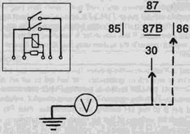
Fig. 10. Voltage being checked at system relay terminals 30 and 86,
5. If voltage is as specified in step 3, check the wiring between the system relay sockets and the following components; the LH control unit connector (pin 21 and pin 9), the air mass meter connector (pin 2 on LH 2.2 or pin 5 on all others), and the fuel pump relay (terminal 86). If no wiring faults can be found, the system relay is probably faulty.
NOTE
On 1985 through 1988 turbo models, a turbo over-pressure switch interrupts power to the fuel pump relay (terminal 86) when the turbocharger's boost pressure gets too high. Check for continuity in the wire between terminal 87 of the system relay socket and terminal 86 of the fuel pump relay socket. If there is no continuity, test the turbo over-pressure switch as described in 234 Fuel Pump and Fuel Tank.
Coolant Temperature Sensor
The coolant temperature sensor sends continuous engine temperature information to the LH control unit. If there is break in the signal from the temperature sensor, the ECU will simulate a fixed signal, and the system will continue to operate based on an engine temperature of 68°F (20°C) on cars with LH 2.2 or 113°F (45°C) on cars with LH 2.4 and LH 2.4.2.
The sensor is mounted in the intake manifold. See Fig. 11. It projects into the cylinder head to measure engine coolant temperature. The sensor has a negative temperature coefficient (NTC), which means that its resistance goes down as its temperature goes up.
To check the sensor, disconnect the harness connector and check the resistance across the sensor terminals. Table g lists sensor resistances based on engine temperature. If any faults are found, the sensor should be replaced as described later under Component Replacement.
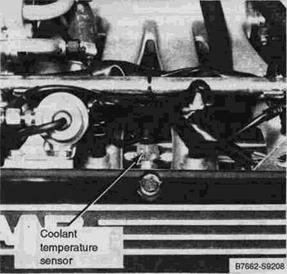
Fig. 11. Coolant temperature sensor.
NOTE
Afaulty coolant temperature sensor will cause a noticeable increase in idle speed, as well as possibly affecting driveability. On LH 2.4 and LH 2.4.2 the Check Engine light should illuminate.
Table g. Coolant Temperature Sensor Resistance
Temperature | Resistance (ohms, ±10%) |
-4°F(-20°C) | 14,000 |
14°F(-10°C) | 9,000 |
32°F (0°C) | 5,800 |
ga'F(io°C) | 3,800 |
SB'F(15°C) | 3,000 |
68°F (20°C) | 2,600 |
76°F(25°C) | 2,000 |
86°F (30 °C) | 1,700 |
176°F(80°C) | 320 |
Throttle Position Sensor
The throttle position sensor is mounted on the side of the throttle housing and is directly connected to the throttle valve shaft. See Fig. 12. The sensor provides a signal to the control unit based on the position of the throttle valve.
On models with LH 2.2 and LH 2.4 fuel injection, there are two switches in the housing that provide a ground signal whenever the throttle is fully closed or fully open.
Fuel Injection 240-13
On models with LH 2.4.2 fuel injection, there is a potentiometer in the housing that changes resistance as the throttle moves. The control unit sends a voltage signal to the position sensor and monitors the voltage that comes back. Resistance decreases (voltage increases) as the throttle opens.
Fig. 13. Throttle position sensor being checked on cars with LH 2 2 and LH 2 4
Fig. 12. Throttle position sensor (arrow) mounted to side of throttle housing
Check throttle position sensor function by disconnecting the harness connector and checking continuity across the terminals while changing the throttle position. See Fig. 13. Table h and Table i list the correct test results. If the results are incorrect, check sensor adjustment as described below under LH Fuel Injection Adjustments. If adjustment does not correct the problem, replace the throttle position sensor
Table i. Throttle Position Sensor Tests—LH 2.4.2
Throttle position | Terminals checked | Test results |
closed | 1 and 3 | ohms |
wide open | 1 and 3 | ohms |
between closed | 1 and 3 | continuously |
and wide open | vanable between | |
ohms, | ||
with no dropouts |
NOTE
On models with LH 2 4 2, the throttle potentiometer is non-adjustable If test results are incorrect, replace the throttle position sensor
Table h. Throttle Position Sensor Tests—LH 2.2 and LH 2.4
Throttle position | Terminals checked | Test results |
closed | 1 and 2 | continuity |
2 and 3 | no continuity | |
half open | 1 and 2 | no continuity |
2 and 3 | no continuity | |
wide open | 1 and 2 | no continuity |
2 and 3 | continuity |
Air Mass Meter
The heart of the LH fuel injection system is the air mass meter. It is located between the air filter and the intake manifold. The air mass meter electronically measures the air entering the engine. The air mass meter has no moving parts.
When the engine is running, a current is used to heat a thin wire in the center of the meter. See Fig. 14. The current flowing through the wire is regulated to maintain a wire temperature that is always 100°C more than that of the cooler air passing over it. The current used to heat the wire is then electronically converted into a precise voltage measurement corresponding to the air entering the engine.
Because the hot wire measures air mass, no other inputs to the control unit are needed for air temperature or altitude. A screen across the meter intake helps protect the wire and also breaks up air flow for more accurate measurements. To keep the wire free from dirt, it is heated to a temperature of about 1000°C (1830°F) for one second. This "burn-off" cycle takes place automatically, four seconds after the engine is turned off.
If the hot wire breaks or if there is no output from the air mass meter, the control unit automatically switches to a "limp-home" mode and turns on the Check Engine light The engine
240-14 Fuel Injection
Fig. 14. Air mass meter
can usually be started and driven. The air mass meter has no internal moving parts and cannot be serviced
To test air mass meter
1. Disconnect the air mass meter from the air cleaner only. Leave it connected to the duct leading to the intake manifold and leave the wiring harness connected
2. Start engine and run it to normal operating temperature
3. Rev the engine to at least 2500 rpm, then shut it off. Look through the front of the meter at the hot wire. After approximately four seconds the wire should glow brightly for about one second.
NOTE
If the wire glows as specified, then the air mass meter and control unit are probably operating correctly If the wire does not glow, continue testing
4 Remove the air mass meter and look through it to see if the wire is broken. It's very small, so check carefully If the wire is broken, the meter will have to be replaced as described below. If the wire is intact, continue testing
5. Reinstall the air mass meter and the harness connector. Peel back the rubber boot from the harness connector Working from the rear of the connector, connect a digital voltmeter across terminals 1 and 4. See Fig. 15.
CAUTION
Use only a digital voltmeter for the above test An analog meter can damage the air mass meter
Fig. 15. Voltmeter connected to air mass meter terminals 1 (-) and 4 (+) to check for meter burn-off voltage
6 Start and rev the engine to at least 2500 rpm, then shut it off. After about 4 seconds, the voltage should rise to about 4 volts for a duration of one second. If the voltage is as specified, but the wire does not glow as described in step 3 above, the air mass meter is faulty and should be replaced.
NOTE
• On models with LH 2 2, a new replacement air mass meter should be adjusted as described below under LH Fuel Injection Adjustments. Air mass meters used on LH 2 4 and 242 do not require any adjustments
• The air mass meter used on LH 2 2 (aluminum body) is not the same meter used on LH 2 4 and LH black plastic body) Do not interchange these meters.
7. If voltage is not present in step 6, turn the ignition key on and check for voltage and ground at the meter's connector. There should be ground at pin 4 There should be positive (+) battery voltage at pin 2 (LH 2.2) or at pin 5 (LH22.LH2.42).
If any faults are found, check for wiring breaks between the air mass meter and the LH control unit and between the air mass meter and the system relay. Also check the operation of the system relay as described above.
Fuel Injectors
The fuel injectors are electrically operated solenoid valves They are switched on and off (open and closed) by the LH control unit. The injectors are connected to a common fuel supply, called the fuel rail. See Fig. 16.
There are a couple of common injector problems. Carbon deposits that form at the tips of injectors will clog them and reduce fuel flow. This often causes rough running, stalling, and power loss. This problem can usually be reduced and controlled through the use of quality gasolines containing deter-
Fuel Injection 240-15
Fig. 16. Fuel rail is common fuel supply and mounting for all four injectors.
gents. If the problem is serious, a Saab dealer or other qualified repair shop has specialized injector cleaning equipment.
A second problem is old and cracked 0-rings. They allow unmeasured air to enter the engine. Since the air is unmeasured, additional fuel is not injected and the mixture is leaned. The LH control unit will usually adapt itself to this extra air, but a symptom of this problem is increased fuel consumption. The injectors must be removed as later described under Component Replacement.
NOTE
Damaged injector 0-rings are just one of many possible causes of increased fuel consumption. For more information see 200 Engine—General.
To test injectors
NOTE
The information below is an electrical test only. The test does not check the spray patterns or fuel supply to the injectors. A Saab dealer or other qualified repair shop can perform such a test as part of the injector cleaning procedure.
1. Disconnect a harness connector from an injector and connect to it an LED test light, an injector tester, or a digital voltmeter across the connector. See Fig. 17. When the engine is cranked, the LED should flash or the following voltage should be present:
Injector cranking voltage (approximate VDC)
• engine temp. 32°F..................... 1 volt
• engine temp. 68°F.................volt
• engine temp. 176°F................volt
CAUTION
Use only a digital voltmeter, an LED test light or an LED injector tester. Use of an analog VOM or incandescent test light may damage the control unit.
Fig. 17. Special LED test light connected across fuel injector connector for voltage test. Simple LED test light or digital VOM can also be used.
NOTE
If the engine runs but you think one injector is bad, place a screwdriver or an automotive stethoscope on the injector. There should be a buzzing or vibration as the engine runs. If the injector is not buzzing, check for voltage to the injector and check its resistance as described below. If the injector is buzzing, very briefly unplug the harness connector from the injector with the engine running. If the injector is working correctly, there should be a noticeable rpm drop.
2. If the light doesn't flash or there is no voltage, check for power to the injector. There should be battery voltage (+) at the blue/red wire of each injector connector with the ignition key on. See Fig. 18. If not, check the wiring to the injector using the wiring diagrams listed in 371 Wiring Diagrams, Fuses and Relays.
NOTE
If there is positive (+) battery voltage as described in step 2, but there was no response through the LED or voltmeter in step 1, check the wire from the control unit to the injectors. If no winng faults can be found, the ground signal from the control unit is missing. See Electrical Checks and Component Testing for additional electrical tests.
3. If power is present as described in the above step, unplug the injector connectors and check the injector resistance. Replace the injector if the resistance is incorrect.
Injectors
• resistance .........ohms at 68°F (20°C)
240-16 Fuel Injection
Pig. 18. Checking power to injector with ignition on Check at red-blue wire of connector
NOTE
Injector resistance will vary slightly depending on temperature In general, the range should be between 10 and 20 ohms
4. If no faults are found up to this point, check the pulse-time regulation function of the control unit. Peel back the rubber boot from the injector connector and connect a voltmeter to the wires in the connector. Start the engine. Check that the voltage decreases as the engine warms up. The values given below are approximate.
Injector warm-up enrichment voltage (VDC)
• engine temp. 32°F..................... 1 volt
• engine temp. 68°F................volt
• engine temp. 176°F...............volt
If the voltage readings are incorrect, check the temperature sensor as described above. Also check the CO reading and the air mass meter burn off function. If these are OK, then either the wiring to the control unit or the control unit itself is faulty. Check the control unit inputs and wiring by making the electrical checks described below under LH Control Unit.
Oxygen Sensor
The oxygen sensor monitors the exhaust gas and provides the LH control unit with feedback about the air-fuel ratio and combustion efficiency. Using this information, the control unit continuously adjusts the air-fuel mixture to ensure optimum dnveability and exhaust emissions.
The oxygen sensor is mounted in the exhaust system. See Fig. 19. The oxygen sensor produces a small voltage (0-1 volt) based on the oxygen content in the exhaust gas as com
pared to the oxygen outside the exhaust pipe. The bigger the differential, the greater the output voltage. When the mixture is rich, there is very little oxygen in the exhaust (high output voltage). When the mixture is lean, there is an excess of oxygen in the exhaust (low output voltage).
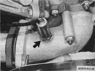
Fig. 19. Location of oxygen sensor (arrow) on turbo model (in exhaust manifold) On non-turbo model, the oxygen sensor is mounted in the front exhaust pipe, near the steering rack
The oxygen sensor must be at a temperature of at least 600°F to generate voltage, so it is electrically heated to help it reach operating temperature more quickly. The oxygen sensor is checked by seeing if it generates a voltage when the engine is idling at normal operating temperature.
To test oxygen sensor
1. Disconnect the sensor's single black wire (sensor signal wire). See Fig. 20.
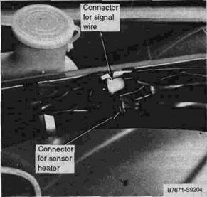
Fig. 20. Oxygen sensor wiring connectors are located on right (passenger) inner fender well, just above battery
Fuel Injection 240-17
2. Connect the positive lead of a voltmeter to the black wire coming from the sensor and connect the negative meter lead to chassis ground. See Fig. 21. Start the car and let it idle. The oxygen sensor should start to produce a fluctuating voltage within a short period.
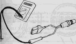
Fig. 21. Oxygen sensor output voltage being checked (shown schematically). Sensor should be installed and the engine should be running,
Oxygen sensor
• voltage at idle ..................to 1 volt
NOTE
To further check sensor response to lean and rich mixtures, slightly open the oil filler cap to create an air leak, or pull the vacuum hose off of the fuel pressure regulator to increase fuel pressure.
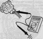
3. If the sensor does not emit a fluctuating voltage, turn the engine off and check the sensor's preheater circuit. Disconnect the two-wire connector and check for battery voltage at the connector with the engine running. If voltage is not present, check the wiring to the preheater and check the preheater fuse. If voltage is present, check the preheater coil resistance. See Fig. 22. If any faults are found, replace the sensor.
NOTE
On 1986 through 1988 models, the preheater fuse is in-line, in the engine compartment on the right-hand side fender. On 1989 and later cars, the fuse is in the main fuse/relay panel (position no. 1). On 1985 models, the preheater is not fuse protected.
Oxygen sensor
• preheater resistance............ .approx. 4 ohms

Fig. 22. Oxygen sensor heating coil resistance being measured (shown schematically).
If the oxygen sensor doesn't produce voltage, and the preheater circuit is OK, replace the sensor.
Tightening Torque • Oxygen sensor.............Nm (29 ft-lb)
NOTE
Coat the oxygen sensor threads with an anti-seize compound before installation. Do not get the compound on the sensor tip. This can damage the sensor.
Automatic idle Control (AIC) System
The AIC system maintains idle speed through the AIC idle control valve. See Fig. 23. The system compensates for engine load and engine operating conditions, so periodic adjustment of the idle speed is unnecessary. The AIC valve is controlled by the LH control unit.
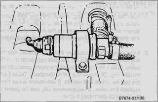
Fig. 23. AIC valve.
240-18 Fuel Injection
The LH control unit monitors engine rpm and other operating conditions such as air conditioning and automatic transmission loads, and then sends an electrical signal to open or close the valve. This changes the amount of air that bypasses the closed throttle valve.
NOTE
If you suspect an intermittent fault, lightly tap the valve while you are testing resistance
NOTE
There are three different idle control valves used on the cars covered by this manual, depending on the fuel system These valves operate differently and are not interchangeable between fuel systems
On LH 2.4 and LH 2 4.2 fuel injection, the AIC function is completely adaptive. The control unit remembers how far the valve was open the last time the engine was at idle and reverts to this as a base setting. In addition, the valves used on these models have a limp-home feature that maintains a fixed idle speed in the event of an AIC valve failure. This idle speed is approximately 1,200 rpm on cars with LH 2.4 and 850 rpm on cars with LH 2 4 2.
Before proceeding with troubleshooting an idle problem, check that the throttle position sensor is working correctly as described earlier under Throttle Position Sensor. On cars with high mileage, enough residue and dirt may collect on the throttle valve plate and bore to restrict air flow and affect the AIC system, remove the AIC valve and the air intake duct from the throttle housing. Clean both the AIC valve and the throttle plate and bore. Reinstall the valve and duct and run the engine to check idle
NOTE
On models with LH 2 2 fuel injection, the base idle may need to be reset after this procedure See LH Fuel Injection Adjustments as described below
Fig. 24. Idle control valve terminals
Table j. AIC Valve Resistance
Fuel System | Test terminals | Resistance (ohms) |
LH22 | 1 and 2 | 20±2 |
2 and 3 | 20±2 | |
1 and 3 | 40±4 | |
LH24 | 1 and 2 | 8±2 |
LH242 | 1 and 2 | 10-15 |
2 and 3 | 10-15 |
3. With the valve's harness connector disconnected, check for voltage at the blue/red wire in the connector When the ignition is turned on there should be approximately battery voltage.
4. If there is no voltage at the connector, check the wiring to the valve's connector. See 371 Wiring Diagrams, Fuses and Relays. |
To test AIC system
1 With the engine running, check that the idle control valve is buzzing. On cars with air conditioning (A/C) or automatic transmission, turn on the A/C or shift the car into drive Idle should remain steady or increase slightly
2 If the valve is not buzzing, or if idle decreases, stop the engine and disconnect the harness connector from the valve. Check the resistance of the valve across its terminals. Fig 24 shows the valve terminals Table j lists the test terminals and results If resistance is incorrect, replace the valve. If resistance is OK, test for power to the valve as described below.
NOTE
On models with LH 2 2 fuel injection, the voltage will be momentary—only for as long as the fuel pump relay is closed To get a constant voltage supply, run the engine
NOTE
On LH 2 2, the AIC valve receives positive (+) battery voltage from the fuel pump relay On LH 2 4 and LH 2 4 2, the valve receives voltage from the system relay
Fuel Injection 240-19
5. If voltage is present as described in step 3, check the wiring between the control unit and the valve and fix any breaks. If no wiring faults are found, check the LH control unit signal to the AIC valve. If the signal to the valve is as specified, the AIC valve is probably faulty and should be replaced.
earlier. Remove the control unit, unplug the connector, and make tests from the back of the connector to avoid damaging connector terminals. See Fig. 25. Control unit connector terminals are shown in Fig. 26. Table k and Table I list the tests and correct test results.
NOTE
• On cars with LH 2 2, the AIC valve control signal can be checked using a duty cycle meter (or dwell meter) as described below under LH Fuel Injection Adjustments.
• On cars with LH 2 4 and LH 2 4 2, the AIC valve control signal can be checked by making the electrical tests outline below under LH Control Unit.
There are some additional inputs to the control unit that affect idle speed (i. e. throttle position, A/C-on signals, and A/T Drive position). To check these signals, make the electrical tests described below under LH Control Unit.
Fig. 25. For access to back of connector terminals when testing disconnect connector and remove rubber gasket
LH Control Unit
The following voltage and continuity tests will help determine whether there are faults in the wiring or components that provide information to the LH control unit. If all inputs and wiring are OK but operational problems still exist, the control unit itself may be faulty.
Generally, a complete absence of voltage or continuity means there is a wiring or connector problem. See 371 Wiring Diagrams, Fuses and Relays for help in diagnosis. Test results with different values than those specified do not necessarily mean that a component is faulty. Check for loose connections or connections that are inadequate due to corrosion or contamination. If the results are still incorrect, test the component itself.
Make these tests at the LH control unit connector using a digital VOM. The control unit is mounted in the passenger compartment, in the passenger-side footwell See Fig. 8 given
Fig. 26. Terminal identification for LH fuel injection control unit connectors Take care not to damage connector terminals with test probes
240-20 Fuel Injection
CAUTION
• Always connect or disconnect the control unit connector and meter probes with the ignition off to avoid damage to electronic components
• On models with LH 2 4 and LH 2 4 2, always wait at least 40 seconds after turning off the ignition before removing the control unit connector If the connector is removed before this time, residual power in the system relay may damage the control unit
NOTE
• On cars with LH 2 4 and LH 2 4 2 fuel injection, disconnecting the control unit connector will erase the control unit's adaptive and diagnostic memory When the engine is restarted it may operate erratically The engine must be driven for at least 30 minutes for the adaptive memory to be reset
• The electrical tests below call for measuring voltage, current or resistance using a digital volt-ohm meter (DVOM) or a multimeter Using an analog meter may damage the control unit or other solid state components
Table k. LH 2.2 Electrical Tests
Component or circuit | Test terminals (Test con | Test conditions | Test value |
ditions at LH connector | |||
unless otherwise noted) | |||
Control unit power (switched), fuse 22 | 18 and ground | Ignition on | Approximately 12 volts |
(battery voltage) | |||
Control unit grounds | 18 and 5, 18 and 11, | Ignition on | Approximately 12 volts |
18 and 25 | (battery voltage) | ||
System relay | Jumper terminals 5 and 21 | System relay closes, power | |
to pin 9, power to pin 2 of air | |||
mass meter | |||
Fuel pump relay | Jumper terminals 5 and 17, | Fuel pump runs, power to | |
(see 234 Fuel Pump and Fuel Tank) | and 21 and 25 | oxygen sensor preheater | |
(blue/red wire), power to | |||
fuel injectors (blue/red wire) | |||
Ignition pulse signal | land 25 | Crank engine | 2-3 volts (VAC) |
Coolant temperature sensor | 2 and 25 | Resistance according to | |
Table g shown earlier | |||
Throttle position sensor | 3 and ground | Throttle closed | Continuity |
Throttle 1/2 open | No continuity | ||
12 and ground | Throttle wide open | Continuity | |
Automatic transmission switch | 4 and 25 | Ignition on, transmission in | Approximately 12 volts |
(see 444 Automatic Transmission | Dnve | (battery voltage) | |
Controls) | |||
AIC valve | 10 and 23 | 40±4 ohms | |
Fuel injectors | 13 and socket 87 of fuel | 4 ohms | |
pump relay | |||
Air conditioning ON signal | 12 and 16 | Jumper sockets 16 and TK | Continuity |
of A/C compressor relay | |||
Oxygen sensor | 20 and 25 | Oxygen sensor connected | No continuity |
Separate connector and | Continuity | ||
connect green wire to | |||
ground | |||
Signal to EZK ignition system (ex turbo | 3 and 24 | Disconnect EZK control unit | Continuity |
models) (see 340 Ignition System) | connector, bridge terminals | ||
7 and 8 of connector |
Fuel Injection 240-21
Table 1. LH 2.4 and LH 2.4.2 Electrical Tests
Component or circuit | Test terminals (at discon | Test conditions | Test value |
nected LH connector un | |||
less otherwise noted) | |||
Control unit power (switched), fuse 22 | 35 and ground | Ignition on | Approximately 12 volts |
(battery voltage) | |||
Control unit power (constant) | 4 and ground | Approximately 12 volts | |
(battery voltage) | |||
Control unit grounds | 4 and 5, 4 and 17 | Approximately 12 volts | |
(battery voltage) | |||
System relay | Jumper terminals 17 and 21 | Relay closes, power to pin | |
9, power to pin 5 of air mass | |||
meter, power to fuel | |||
injectors (blue/red wire) | |||
Fuel pump relay (see 234 Fuel Pump and | Jumper terminals 5 and 20, | Fuel pump runs, power to | |
Fuel Tank), power from system relay, | and 17 and 21 | blue-red wire at oxygen | |
oxygen sensor heater power | sensor connector | ||
Ignition pulse signal (LH 2.4) | 1 and 17 | Crank engine | 2-3 volts (VAC) |
Ignition pulse signal (LH 2.4.2) | 1 and 17 | Crank engine | 6.5 volts (VAC) |
Coolant temperature sensor | 13 and 17 | Resistance according to | |
Table g shown earlier | |||
Throttle position sensor (LH 2.4) | 2 and ground | Throttle closed | Continuity |
Throttle 1/2 open | No continuity | ||
3 and ground | Throttle wide open | Continuity | |
Throttle potentiometer (LH 2.4.2) | 2 and 10 | Resistance according to | |
Table i shown earlier | |||
Automatic transmission switch, (see 444 | 30 and 17 | Ignition on, transmission in | Approximately 12 volts |
Automatic Transmission Controls) | Drive | (battery voltage) | |
AIC valve (LH 2.4) | 33 and 17 | LH control unit connector | Approximately 8 volts at |
connected, engine running, | idle. Voltage should drop as | ||
probe terminals from rear of | load increases | ||
connector | |||
AIC valve (LH 2.4.2) | 33 and 17 | LH control unit connector | Approximately 7 volts at |
connected, engine running, | idle. Voltage should drop as | ||
probe terminals from rear of | load increases | ||
connector | |||
Fuel injectors | 18 and socket 87 of system | 4 ohms | |
relay | |||
Air conditioning ON signal (LH 2.4) | 14 and ground | LH control unit connector | less than 0.1 volt with A/C |
connected, engine running, | off and battery voltage with | ||
probe terminals from rear of | A/Con. | ||
connector | |||
Air conditioning ON signal (LH 2.4) | 14 and groundn and | LH control unit connector | less than 0.1 volt with A/C |
ground | connected, engine running, | off and battery voltage with | |
probe terminals from rear of | A/Con. | ||
connector | |||
Oxygen sensor | 24 and 17 | Oxygen sensor connected | No continuity |
Separate connector and | Continuity | ||
connect green wire to | |||
ground | |||
EGR modulating valve (where applicable— | 19 and 17 | Ignition on | Approximately 12 volts |
see 254 Exhaust Emission Control) | (battery voltage) |
continued on next page
240-22 Fuel Injection
Table 1. LH 2.4 and LH 2.4.2 Electrical Tests (continued)
Component or circuit | Test terminals (at discon | Test conditions | Test value |
nected LH connector un | |||
less otherwise noted) | |||
EGR valve temperature sensor (where | 23 and 17 | Run engine at operating | Resistance should measure |
applicable—see 254 Exhaust Emission | temperature Turn off | several megohms | |
Control) | engine and disconnect | ||
control unit connector (after | |||
waiting 45 seconds) | |||
Charcoal canister purge valve(ELCD) (see | 27 and 17 | Ignition on | Approximately 12 volts |
254 Exhaust Emission Control) | (battery voltage) | ||
Vehicle speed sensor | 34 and ground | Ignition on, raise front of car | Voltage alternates between |
and rotate front left wheel | 05and50volts | ||
slowly | |||
Upshift light | Jumper 26 and 17 | Ignition on | Light illuminates |
Check Engine light | Jumper 22 and 17 | Ignition on | Light illuminates |
COMPONENT REPLACEMENT
To remove LH control unit
1. Disconnect the negative (-) battery cable.
2. Remove the door sill plate from the passenger side of the car. Peel up the lower front edge of the door weather stripping.
3 Remove the trim plate holding the carpet to the front side panel and peel the carpet until the control unit and relays are visible.
4. Unplug the control unit harness connector by releasing the fastener and then pivoting the connector up and off of the unit.
5. Remove the mounting screws holding the control unit to the body.
Installation is the reverse of removal.
To remove coolant temperature sensor
1. Detach the crankcase ventilation hose from the valve cover
2 Unbolt the fuel pressure regulator and its mounting bracket from the cylinder head and push it to one side.
NOTE
On some models, it may be necessary to remove the regulator completely for access to the temperature sensor
3. Drain approximately 4 quarts of coolant from the cooling system. This is so that coolant will not leak out when the sensor is removed. See 261 Radiator and Cooling System.
4. Disconnect the sensor wiring and remove the sensor using a 3/4 in deep-well socket.
5. Before installing the new sensor, check the mating surface on the intake manifold Use a new copper sealing washer.
Tightening torque
• Coolant temperature sensor....Nm (15 ft-lb)
Installation is the reverse of removal. Refit the pressure regulator and crankcase ventilation hose. Make sure the LH system grounds are properly replaced on the pressure regulator mounting.
To remove throttle position sensor
1. Unplug the harness connector from the sensor. See Fig 12 given earlier
2. Remove the mounting screws holding the sensor to the side of the throttle housing.
Installation is the reverse of removal. On LH 2.2 and LH 2 4, the switch must be adjusted as described below under LH Fuel Injection Adjustments.
To remove air mass meter
1. Loosen the large hose clamp securing the rubber duct to the air mass meter.
Fuel Injection 240-23
2. Disconnect the harness connector from the meter.
3. Release the two spring clip fasteners from the air cleaner housing cover. See Fig. 27. Remove the air mass meter from the duct and cover.
WARNING
Wrap a clean shop towel around the banjo bolts before loosening them.
Fig. 27. Air mass meter and spring clip.
Installation is the reverse of removal. Where applicable, make sure the ridge in the air mass meter and the recess in the air cleaner cover are aligned before fastening the spring clips.
To remove fuel injectors
WARNING
Fuel will be expelled when fuel lines are disconnected. Do not smoke or work near heaters or other fire hazards. Keep a fire extinguisher handy.
CAUTION
Absolute cleanliness is essential when working with fuel circuit components. Even a minute particle of dirt can cause trouble if it reaches an injector. Thoroughly clean the unions before disconnecting any fuel lines. Use clean tools.
CAUTION
To prevent damaging the fuel rail assembly, use an open-end wrench on the flats on the rail to hold it steady while loosening the fuel lines.
Fig. 28. Fuel rail assembly and fuel lines (arrows).
4. Remove the bolts that hold the fuel rail to the intake manifold and pull the fuel rail away complete with injectors.
5. To remove the injectors from the fuel rail, pry off the retaining clips, then twist the injectors slightly and pull them off.
When installing the injectors, fit new 0-rings to the injectors. For ease of installation, lightly lubricate the 0-rings with petroleum jelly. Install the injectors to the fuel rail but do not install the retaining clips. Position the fuel rail and injectors on the intake manifold. Make sure that injectors and the fuel rail are fully seated and then install the retaining clips and mounting bolts. Reconnect the fuel hoses to the fuel rail. Reconnect the crankcase ventilation hose.
To remove fuel pressure regulator
1. Detach the crankcase ventilation hose from the valve cover.
2. Unplug the wiring harness connectors from the injectors. Free the wiring harness from the fuel rail by undoing the clips. Carefully pull the harness to the side.
3. Disconnect the fuel inlet and outlet hoses on the fuel rail by removing the banjo bolts. See Fig. 28.
WARNING
Fuel under pressure will be expelled when fuel lines are disconnected. Do not smoke or work near heaters or other fire hazards. Keep a fire extinguisher handy.
1. Disconnect the vacuum hose from the regulator.
240-24 Fuel Injection
2. Disconnect from the regulator the fuel hose coming from the fuel rail.
3. Remove the fuel pressure regulator mounting bolts and lift out the regulator and its bracket. Disconnect the fuel return hose from the regulator. Remove the regulator from the bracket.
Installation is the reverse of removal. Remember to reconnect the ground wires to the fuel pressure regulator mounting bolt.
To remove AIC valve
1. Disconnect the harness connector from the AIC valve.
2. Loosen the valve's hose clamps and disconnect the hoses from the valve. See Fig. 29.

Fig. 29. AIC valve hose clamp being loosened
3. Remove the valve bracket mounting bolt and remove the valve from the bracket.
Installation is reverse of removal. On models with LH 2.2, adjust the base setting of the valve as described below.
LH FUEL INJECTION ADJUSTMENTS
Except for the adjustment of the throttle position sensor, all of the adjustment described below are for cars with LH 2.2 only. Cars with LH 2.4 and LH 2.4.2 are fully adaptive and do not require any adjustments.
Setting the base idle speed ensures that the AIC idle control valve is operating in about the middle of its range under normal conditions. Base idle speed is set at the factory and does not normally need to be checked or adjusted, unless repairs are made to the throttle valve or housing.
Base idle speed is set by reading the control unit signal to the valve. This signal is known as the duty cycle. It is the ratio of on-time to off-time of voltage and is expressed as a percentage. It is measured using a duty cycle or dwell meter.
NOTE
• Remember that 100% on a duty cycle meter corresponds to 90° on a dwell meter
• The test meter must be a quality digital dwell meter, with an accuracy of at least 0 5%. Using an inexpensive analog meter that has an error of 2° would result in a setting 25% out of calibration
To adjust AIC valve and basic idle speed (LH 2.2)
NOTE
For the most accurate adjustment, the engine should be at operating temperature, the ignition timing and idle mixture should be checked and adjusted if necessary.
1. Back off the dashpot so that the plunger no longer contacts the throttle lever. See Fig. 30. Check that there is slack in the accelerator cable. If necessary, loosen the cable.
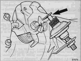
Fig. 30. Dashpot plunger should be backed off throttle lever (arrow)
2. Loosen the screws for the throttle position sensor so that it doesn't affect the throttle valve. Disconnect the sensor harness connector and connect a jumper wire as shown in Fig. 31. This will simulate a closed-throttle signal.
Fuel Injection 240-2S
|
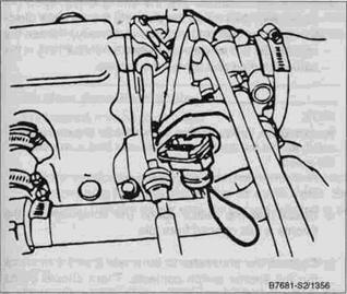
Fig. 31. Jumper terminals 1 (gray wire) and 2 (black-white wire) of throttle position sensor connector. Connect wire from back of connector to prevent damage to terminals. |
|
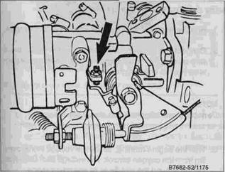
Fig. 32. Throttle stop screw and locknut (arrow). 4. Working from the rear of the AIC valve's harness connector, connect the dwell meter to terminals 2 and 3. See Fig. 33. Connect the tachometer. 5. Start the engine and let it run until the radiator fan cycles at least once. |
3. Loosen the throttle stop screw locknut and back out the screw until it is no longer contacting the throttle lever. See Fig. 32. Thread the screw in until it touches the lever then turn it an additional 3/4 turn. Tighten the lock-nut.
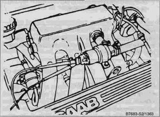
Fig. 33. Meter leads connected to idle control valve terminals 2 and 3 (valve terminal 4 and 5).
NOTE
Make sure all other electrical accessories on the car are off. Make all adjustments to idle only when the fan is off.
6. Depending on the throttle housing, turn either the throttle valve stop screw (Fig. 32) or the throttle valve air bleed screw (Fig. 34) out until the duty cycle is 38% (34° dwell).
NOTE
If the correct reading cannot be obtained, check for intake air leaks or other engine problems.
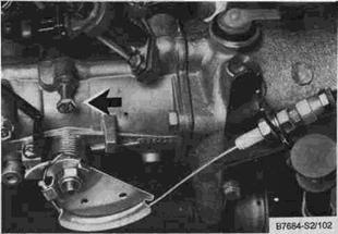
Fig. 34. Throttle valve air bleed screw (arrow) used on early models. Later models with LH 2.2 do not have this screw.
240-26 Fuel Injection
7. Next, turn the screw back in until the meter reading is as specified in the table below.
NOTE
When the correct reading is obtained, the base idle speed should be 850±50 rpm. If it isn't, check for intake air leaks or other engine problems.
Base Idle Speed (at 850+50 rpm)
• Duty cycle............................. 33%
• Dwell.................................. 30°
8. Lock the adjusting screw and recheck the reading.
9. Turn off the engine and remove all test equipment. Reset the dashpot and throttle switch as described below
To adjust throttle position sensor (LH 2.2 and LH 2.4)
The throttle position sensor has two switches in the housing that provide a ground signal whenever the throttle is fully closed or fully open.
1. Loosen the switch mounting screws.
2. Attach a VOM to terminals 1 and 2 of the switch to measure continuity. See Fig. 35.
Fig. 35. Ohmmeter shown connected to throttle position sensor.
3. Rotate the switch so that the switch is just open (no continuity), then rotate the switch in the opposite direction until the switch just closes (continuity). Rotate the switch a bit further (approximately.5 mm/.020 in.) in the same direction and tighten the screws.
NOTE
Rotation of the throttle position sensor too far can cause the switch to hold the throttle open. This may lead to excessive idle speed.
4. Check that the switch opens (no continuity) as the throttle is just opened from idle.
5. Connect the ohmmeter to terminals 2 and 3 to check the full throttle switch contacts. There should be no continuity until the switch is almost fully open. At 72° of open throttle, the switch should close (continuity). If the contacts do not close, the switch should be replaced.
To check basic setting of fuel injection system (LH 2.2)
The procedure below should only be carried out when the engine function has been disturbed, such as for the replacement of the air mass meter or after major engine work has been completed. Saab does not recommend any specified interval for this check. For the most accurate results, a high-quality digital multimeter should be used.
1. Run the engine until it reaches operating temperature.
2. Connect the positive lead of a voltmeter to the black wire coming from the oxygen sensor. Connect the negative lead to chassis ground.
NOTE
Do not disconnect the wires from the oxygen sensor.
3. With the engine running, check the voltage signal coming from the oxygen sensor. The voltage should be fluctuating around the middle of its operating range.
Oxygen sensor • voltage at idle, engine fully warmed........ approx. 0.5 volts (fluctuating)
NOTE
If the sensor is not putting out a signal or if the signal is not fluctuating, make sure the oxygen sensor system is functioning correctly as described earlier under Oxygen Sensor.
Fuel Injection 240-27
4. If the voltage is too high or too low, turn the engine off and remove the harness connector from the air mass meter. Connect a digital ohmmeter across terminals 3 and 6 of the meter and measure the resistance.
Air Mass Meter Base Setting • resistance measured at meter terminals 3 and 6.................ohms
5. If the resistance reading is incorrect, remove the anti-tamper plug from the side of the air mass meter. See Fig. 36. Turn the screw until the correct reading is obtained.
NOTE
If a reading of 380 ohms cannot be obtained, the air mass meter is faulty and should be replaced.
8. Install a new anti-tamper plug anti-tamper plug from the side of the air mass meter.
If the correct oxygen sensor reading still cannot be obtained, check the wiring between the air mass meter and the control unit. Test the oxygen sensor and its circuit. Try substituting a known good air mass meter or oxygen sensor. If no faults can be found, the LH control unit may be faulty.
To adjust dashpot (LH 2.2)
The dashpot is mounted to the throttle housing and holds the throttle valve open for a moment when the throttle is closed suddenly. This helps reduce the exhaust emission of unburned fuel. A defective or misadjusted dashpot may be the cause of a high idle or the cause of an idle that takes a long time to return to normal when the throttle is released.
NOTE
Before making the adjustment below, check that the basic throttle adjustment is correct.
|
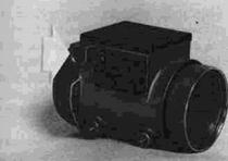
Fig. 36. Air mass meter anti-tamper plug (arrow), |
1. With the engine at operating temperature, rev the engine up to at least 3000 rpm, then release the throttle and check that the engine speed returns to normal within 3 to 6 seconds. If the dashpot fails this test, proceed with dashpot adjustment. 2. Loosen the dashpot locknut and turn the dashpot so that its operating rod moves away from the throttle lever. See Fig. 29 above. 3. Rev the engine up to the speed given below and hold the engine speed steady. Turn the dashpot in until its rod just touches the throttle lever. See Table n. Tighten the locknut. Table n. Dashpot Adjustment Specifications |
6. Reconnect the harness connector and start the car. Recheckthe voltage signal at the oxygen sensor as described above. The voltage should now be fluctuating around the middle of its operating range (approximately 0.5 volts)
7. If the sensor voltage is incorrect, adjust the screw in the side of the air mass meter until the oxygen sensor voltage is correct.
Model | Speed at which dashpot rod |
touches throttle lever | |
Non-turbo | 2500±100 rpm |
Turbo | 2600±100 rpm |
4. Recheck dashpot operation. If it still fails the test, replace it.
