

Партнерка на США и Канаду по недвижимости, выплаты в крипто
- 30% recurring commission
- Выплаты в USDT
- Вывод каждую неделю
- Комиссия до 5 лет за каждого referral
TM-D223 Service Manual
Contents
Chapter IЎЎЎЎЎЎЎЎЎЎЎЎЎЎЎЎЎЎ..............ЎЎЎЎЎЎЎЎЎЎЎ.Ў.2
1.1 ID PicturesЎЎЎЎЎЎЎЎЎЎЎЎЎЎЎЎЎЎЎЎЎЎЎЎЎЎЎЎЎЎЎ.Ў2
1.2 Platform IntroductionЎЎЎЎЎЎЎЎЎЎЎЎЎ..............ЎЎЎЎЎ.ЎЎЎЎЎЎ3
1.3 Function introductionЎ ЎЎЎЎЎЎЎЎЎЎЎЎЎЎЎЎ................ЎЎЎЎЎ.Ў3
1.4 Hardware System DiagramЎЎЎЎЎЎЎЎЎЎЎЎЎЎ.................ЎЎЎЎЎ.Ў.3
Chapter II Assembly and the demolition ProcessЎЎ.........................ЎЎЎЎЎЎЎ4
2.1 Assembly ProcessЎЎЎЎЎЎЎЎЎЎЎЎЎЎ.ЎЎ.............ЎЎЎЎЎЎЎЎЎ5
2.2 Demolition ProcessЎЎЎЎЎЎЎЎЎЎЎЎЎЎЎ..........Ў...ЎЎЎЎЎЎЎЎ..10
Chapter III Part of the logicЈЁ G networkЈ©ЎЎЎЎЎЎЎЎ......................ЎЎЎ.12
3.1 Power ManagementЎЎЎЎЎЎЎЎЎЎЎЎЎЎЎЎЎЎ.............ЎЎЎЎЎЎ12
3.1.1 Power on/off processЎЎЎЎЎЎЎЎЎЎЎЎЎЎЎЎ........................Ў.12
3.1.2 Charging processЎЎЎЎЎЎЎЎЎЎЎЎЎЎЎЎЎЎ.............ЎЎЎ...14
3.1.3 Battery voltage DetectionЎЎЎЎЎЎЎЎЎЎЎ....................ЎЎЎЎЎ..14
3.1.4 Backup PowerЎЎЎЎЎЎЎЎЎЎЎЎЎЎЎЎ............ЎЎЎЎЎЎЎ.15
3.2 LCD display CircuitЎЎLCDЎЎЎЎЎЎЎЎЎЎЎЎЎ................ЎЎЎ..ЎЎЎ15
3.2.1 LCD interfaceЎLCDЎЎЎЎЎЎЎЎЎЎЎЎ.Ў....ЎЎЎЎЎЎЎ..ЎЎ15
3.2.2 Backlight driverЎЎЎЎЎЎЎЎЎЎЎЎЎЎЎ............ЎЎЎЎЎЎЎЎ16
3.3 Audio circuit ЎЎЎЎЎЎЎЎЎЎЎЎЎЎЎЎЎЎ............ЎЎЎЎЎЎЎЎЎ..17
3.3.1 Handset sending & receivingЎЎЎЎЎЎЎ..Ў..............................ЎЎЎЎ17
3.3.2 Headphones sending & receiving ЎЎЎЎЎ............................ЎЎЎЎЎЎ18
3.3.3 Audio amplifier ЎЎЎЎЎЎЎЎЎЎЎЎЎ.Ў....................ЎЎЎЎЎЎЎ18
3.4 Vibrator Vibration ЎЎЎЎЎЎЎЎЎЎЎЎЎЎЎ..............ЎЎЎЎЎЎЎЎЎ..19
3.5 SIM& UIM card circuit ЎЎЎЎЎЎЎЎЎЎ...........................ЎЎЎЎЎЎЎЎ.19
3.6 Camera InterfaceЎЎЎЎЎЎЎЎЎЎЎЎЎ....................ЎЎЎЎЎЎЎЎЎЎ20
Chapter IV of the logic (C network)ЎЎЎЎЎЎЎ...............................ЎЎЎЎЎЎ21
Chapter ўх TroubleshootingЎЎЎЎЎЎЎЎЎЎЎЎ...............ЎЎЎЎЎЎЎЎ.22
5.1 No displayЎЎЎЎЎЎЎЎЎЎЎЎЎЎЎЎЎЎЎ...............ЎЎЎЎЎЎЎЎ..22
5.2 Handset no sendingЎЎЎЎЎЎЎЎЎЎЎЎЎЎЎ............................ЎЎЎЎ..22
5.3 Handset no receivingЎЎЎЎЎЎЎЎЎЎЎЎЎЎ...................................ЎЎЎ22
5.4 Headphones no sending and receivingЎЎЎЎЎЎ...................................ЎЎЎ.22
5.5 No vibrationЎЎЎЎЎЎЎЎЎЎЎЎЎЎЎЎЎЎЎЎ.............ЎЎЎЎЎЎ....22
5.6 Camera not workЎЎЎЎЎЎЎЎЎЎЎЎЎЎЎЎЎЎЎЎЎЎ.ЎЎЎЎЎЎ22
5.7 Can not power onЎ...............ЎЎЎЎЎЎЎЎЎЎЎЎЎЎ........................ЎЎ.22
5.8 No Signal, week signal, cannot search network ЎЎЎЎЎЎЎЎЎ..............ЎЎ23
Chapter I Brief Introduction
1.1 ID
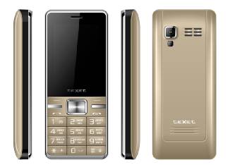
1.2 Platform Introduction
CGC12 is one of GSM models recently launched by our company. As for G-band network, this model used Spreadtrum SC6531D digital base band processor and SC2661D in RF part.
1.3 Function Introduction
* Simple stylish design, built-in antennaЈ»
* Support dual SIM card (GSM) standby & working signal,
* 0.08M pixel cameraЈ»
* MP3ЎўMP4ЈЁvoice &video simultaneously Ј©ЈAMR recorder, stereo playЈ»
* Support T-Flash cardЈ»
* USB 1.1 Ј»
* Bluetooth and FM radio ;
1.4 Hardware System Diagram
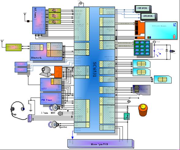
Hardware system diagram
Chapter II Assembly and the demolition process
1.1 Assembly
1. Overall viewing of Device
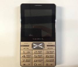

2.Drill out the screws of device, and disassemble the below 2 parts of front cover set.
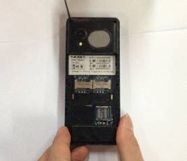
3. Take off the conductive cloth and High temperature resistance insulation tape of LCD plate.
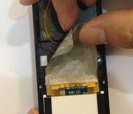
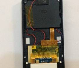
4. Open the front cover set, please put the 2 parts on face side, and soldering LCD. In this process, please donЎЇt touch screen inside and LCD glass. Put the LCD at flat desk and stick the protection film on LCD glass. 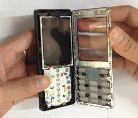
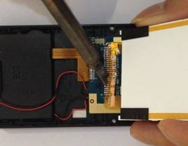
4.Follow the operation of below picture, take off the PCBA Board from battery container, then take off the speaker holder. 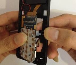
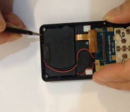
5. Take off Speaker from the holder.
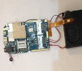
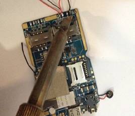
6.Take off receiver and Motor.
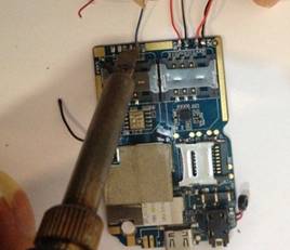
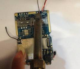
7.Take off MIC and Bluetooth cable.
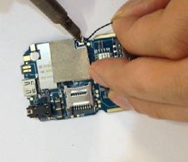
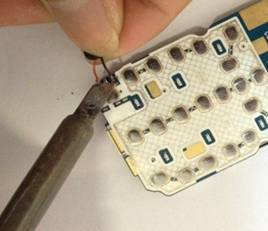
8. Take off DOME Slice, all material parts is disassembled. 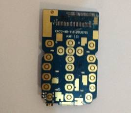
Remark: Please pay attention to the positive and negative pole of each material and position of every material.
Chapter ўу part of logicЈЁG networkЈ©
3.1 Power management
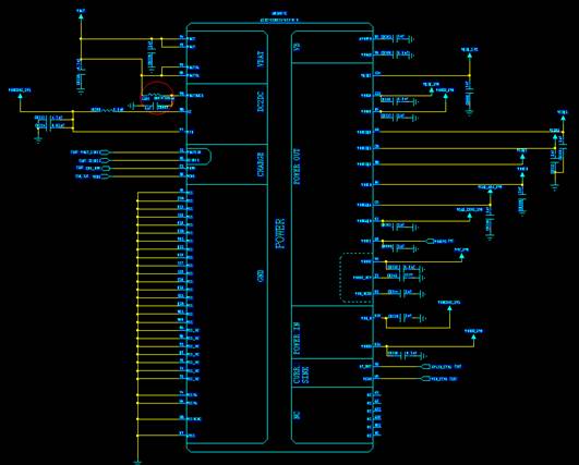
Power Management
Power management is included in SC6531(MCU): Be for Power on & off process, charging process, voltage converters, battery voltage detection, backup power, SIM card interfaces, and vibrator lcm&keypad backlight control.
3.1.1 Power on &off
When powering on, PWRKEY will drop-down, and 6531's internal logic gate will be open and the internal LDO will output voltage later. After return, RESET signal will be pull highly. BB_wakeup will maintain internal logic open status after CPU return, and PWRKEY will be released at that time. When powering off, press PWRKEY, then software will release PWRKEY after vibration and software will activate power off procedure and release BB_wakeup and closed PMIC internal parts.

3.1.2 Charging process
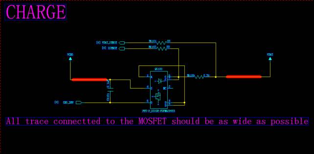
SC6531 provides a almost complete charge management system, and various of battery type can be selected according to BATUSE pin. The current commonly used lithium batteries, used constant pressure (CCCV) of charging. The process can generally be divided into three: pre-charge mode, constant current charging, and the constant pressure charge;
3.2 LCD display Circuit LCD
3.2.1 LCD interface LCD
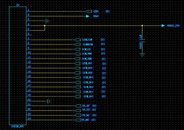
LCD interface circuit
Pin definition: LCM_D00- LCM_D07: transfer orders or display data, LCMRSTN: reset signals; LCM_RDN & LCM_WEN, reading and writing orders; data or order recognition; LCM_CSN, select signal; VBAT backlight for the cathode; LED - for the negative;
3.2.2 backlight driver
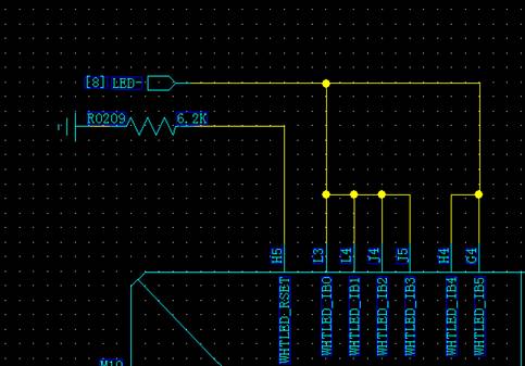
Backlight driver circuit
3.3 Audio circuit
3.3.1 Handset sending & receiving
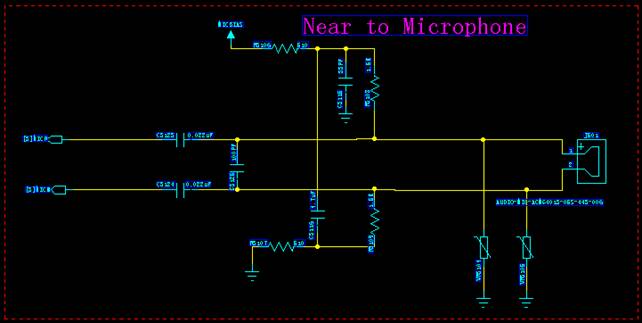
Handset sending circuit
Microphone turns the voice signal into a voltage signal, and sends into CPU module MICP and MICN via audio filter C3123 and C3124 respectively. The audio module will deal with sending accordingly. Since the phone using a capacitive Mike, it is necessary to increase bias voltage, which provided by the internal audio module in CPU to make it work.
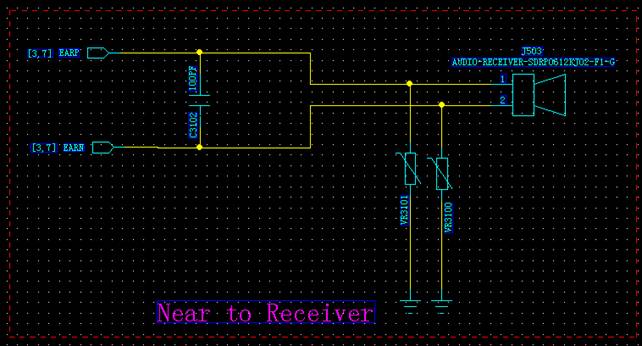
Handset receiving circuit
two opposite phase of voice-voltage signal from CPU (Anode and cathode) go through
3.3.2 Headphones sending & receiving
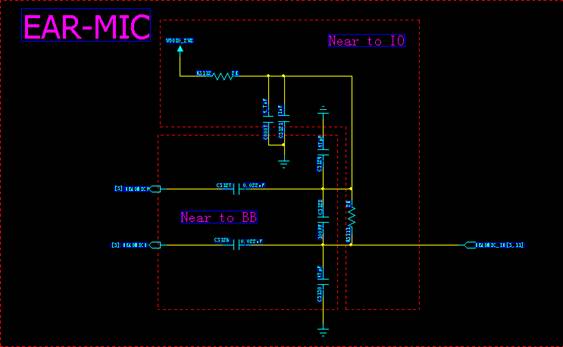
Headphones sending & receiving
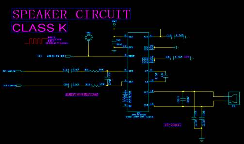
3.3.3 Audio amplifier
3.4 vibrators

Vibrator vibration circuit
3.5 SIM card circuit
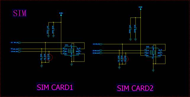
SIM card circuit
The CPU of SIM card firstly input all signals into SC6531, and transfer signals to SIM through its internal logic level to enable SIM auto-detection for different power supply. When handset with SIM card powering on, SIMSEL level is low.
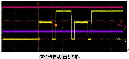
SC6531 provides 1.8 V logic level for SIM card. When SIMSEL level is high,3V logic level will be provided. The responding level for SIM is available. The below picture is detection wave of SIM card under 3V power supply.
3.6 Camera Interface
This unit use 0.08M pixel camera, which the external camera module are connected with and connected to the CPU. The pins are defined as follows: CMMCLK, master clock input; CMPDN, can enter the terminal, often under conditions of HIGH level; CMPCLK, image output clock; CMDATA0 ~ CMATA7, image data output; CMVREF, Y Direction synchronous data output; CMVREF, X direction synchronous data output; GPIO33_SDA, 12C total data input & output; GPIO32_SCL, 12C total clock input; CMRST, external reset input, effective at low level; VCAM_ANA_2V8, digital Power input; VCAM_ANA_2V8, analogue power input.
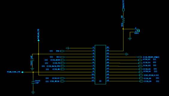
Camera interface circuit
Chapter ўх Troubleshooting
5.1 No display
5.1.1 Replace the LCM to check if there is defect;
5.1.2 Check LCM pad to see whether there is unsoldering;
5.1.3 Replace the CPU to check if there is defect;
5.2 handset no sending
5.2.1 If echo circuit testing is OK in default mode, the circuit between MIC and CPU is OK. Then check the CPU and RF relevant circuit. |
5.3 handset no receiving
5.3.1 Make sure the receiving is normal in default speaker and standby mode. If OK, make sure the circuit between RF and CPU work.
5.3.2 Make sure the receiver and condenser MIC are passed.
5.4 headphones no sending and receiving
5.4.1 Firstly check headphones and the connector;
5.4.2 check the external circuit soldering connected with headphone;
5.4.3 Check related channels about HEAD_R, HEAD_L, HEAD_MIC, and the corresponding MICBIASP by measuring the voltage waveform. Make sure there is no unsoldering and damage etc.
5.5 No vibration
5.5.1 Check the vibrator firstly;
5.5.2 Check the vibrator control signal VIB;
5.5.3 Check the motor control signal VIB on SC6531 and VBAT high and low level and battery voltage output;
5.6 Camera not work
5.6.1 Replace the camera to check if there is defect;
5.6.2 Test related circuit to see whether voltage clock, data, reset signal is normal;
5.7 Cannot power on
Use digital power supply while detection.
5.8.1 If "cannot power on sometimes," check the battery connector;
5.8.2 If Ў°cannot power on all the time Ў° ,generally there are different phenomena as below;
a: if the current value is 0, make sure the battery connection, PWRKEY signal, the power output of SC6531 are normal;
b: If the current value and SC6531 detected power output fluctuate, check whether PWRKEY and SYSRST fluctuate or not, and if the measurement of the power output SC6531 is lower, may be the power supply caused the problem.
C:If there is all OK below, please replace SC6531;
5.8 No signal, week signal, cannot search network
5.9.1 Make sure the antenna contact plate and around circuit are well connected.
5.9.2 Make sure the RF circuit is OK if no signal and cannot connect with network.
5.9.3 Make sure the SIM card be fully contacted with SIM card slot and the check SIM card slot and casing, otherwise there will be continuing weak signal, and continual changes and instant pause while searching network signal.
