

Партнерка на США и Канаду по недвижимости, выплаты в крипто
- 30% recurring commission
- Выплаты в USDT
- Вывод каждую неделю
- Комиссия до 5 лет за каждого referral
Jonusas R. Juzenas E. Juzenas K. Каунасский технологический университет, Литва
| УДК 62.755 Research of Vibrations and Complicated Dynamical Situations in Complex Rotary Systems В процессе эксплуатации сложных роторных систем имеют место деградационные тенденции, приводящие к увеличению уровня виброактивности, снижению качества функциональности сложной роторной системы. Анализ вибрации таких систем позволяет оценить их динамическое состояние. Методом математического моделирования исследованы динамические ситуации сложной роторной системы. Это актуально, так как датчики вибрации, как правило, установлены на корпусах подшипников или непосредственно в подшипниках и по их сигналам трудно судить о динамическом поведении отдельных элементов, расположенных в доли от опор роторов. |
Mechanical vibrations of typical complex rotary systems are generated by several rotors, clutches, gear drives, rolling or sliding bearings and other sources [1, 2]. Degradation process emerging during exploitation of systems is caused by various sources and is followed by increased vibration activity, temperature of various elements, changes of oil tribological properties and lower quality or quantity of production. Therefore, the analysis of vibrations, modelling of dynamical various situations and analysis of vibrations are essential tools for monitoring and controlling complex rotary machines. These tools enable foreseeing of potentially harmful situations, faults detection and lowering of the influence of degradation processes and predicting of reliability of complex rotary systems [2-7].
Object of Research. Object of this research is a complex technological machine GTT3 (Fig. 1). It consists of 0.8 MW electric motor, a steam - fusion gas turbine - axial compressor, a centrifugal compressor and a mechanical reducer. Its all three rotors (electric motor, turbine and centrifugal compressor) run on pressurised hydrodynamic elliptical bearings. Regular operational frequencies of the rotors are between their first and the second natural frequencies. The nominal, rotation of the electric motor is 3000 r/min, turbine - axial compressor – 5200 r/min and centrifugal compressor – 7500 r/min. The first critical speed of the electric motor is 1800 r/min, turbine- axial compressor – 3110 r/min and centrifugal compressor – 3600 r/min.
An especially urgent problem is to decrease vibrations of the rotor of a centrifugal compressor with two impellers having blades mounted on it because it runs at the highest speed. To avoid unexpected breakdown situations and to predict possible failures the vibrations have been measured and numerically modelled. The experiments and experimental results are discussed further. A dynamic model includes a rotor of the reducer with its supports (Fig. 2).
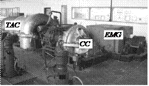
Fig. 1. General view of GTT3 compressor.
EMG – electric motor-generator, CC – centrifugal compressor, TAC – turbine-axial compressor
Dynamic model. The dynamic equation of the compressor rotor has been set up applying numerical modelling [1, 4]. The rotor of centrifugal compressor GTT3 and the adjacent gear shaft of the reducer are divided into 18 elements and analysed as a system of flexible rotors (Fig. 2). Each element has 4 degrees of freedom.
The equation characterizing forced vibrations of the modelled rotor is:
 (1)
(1)
here M is matrix of rotor masses; M’ is matrix of masses characterizing rotation of the rotor cross-sections around the axes of a coordinate system; G is gyroscopic matrix; C is damping matrix; K is stiffness matrix; U is matrix of rotor elements displacements; F is matrix of forces affecting the rotor; w is angular velocity of the rotor. M matrix represents the masses of beam elements and matrix M’ allows evaluating the rotation of their cross-sections. The structure of matrix F depends on the type of exciting forces. Usually those forces are caused by unbalances, anisotropy and deformations of certain rotors and their elements. The affecting forces also are created by other sources of excitation: by hydrodynamic processes in machine sliding bearings, defects in rotors centering, defects of gearwheels and their assemblage, etc. The detailed descriptions of a dynamical model and the structure of matrixes have been presented in earlier works [5].
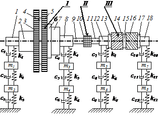
Fig. 2. Dynamic model of centrifugal compressor and reducer rotors: I – centrifugal compressor rotor, II – coupling, III – gear shaft with chevron gears, mi, ki, ci – masses, stiffness and damping coefficients of rotor supports, respectively 1 – 18 structural
elements of rotors
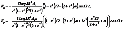
Forces, acting elements on hydrodynamic bearings in x and y directions may be described as follows [1, 5]:
 (2)
(2)
Here l is length of bearing,  is dynamic viscosity of lubricant, R is radius of rotor journal, Ac is characteristic gap of bearing (in the model it is equal to amplitude of vibrations, which is function of time), ε is eccentricity ration, w is angular speed of rotor journal orbiting and c is radial gap of bearing.
Typical results obtained from the modelling presented in Figs 3 and 4.
|
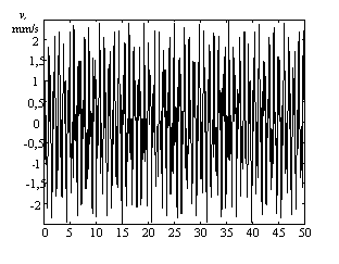
Fig. 3. Modelled time domain signal of the centrifugal compressor’s bearing vibrations in the vertical direction. Exploitation conditions are in a regular range, frequency of rotation – 125 Hz
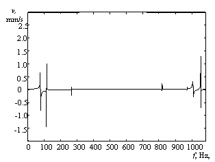
Fig. 4. Spectrum of centrifugal compressor vibrations, frequency of rotation – 125 Hz
Experimental research. The analysis of experimentally measured spectral characteristics of the rotor supports vibrations has shown that there are low frequency components generated by unbalances, anisotropy of the rotor structure, deviations of rotor centering, etc. There are also high frequency components generated by deviations of positioning of a reducer gearwheel. Example of gearwheel failure due to improper centering is presented in Fig. 5.

Fig. 5. Typical defects of gearwheel caused by improper centering
These deviations are caused by the defects of gears incurred during manufacture and assembly. Therefore, periodic measurements of vibrations have been performed in a quite wide range of frequencies (0 – 7500 Hz) aiming to collect more comprehensive data.
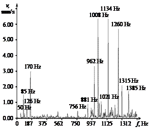
Fig. 5. Spectrum of the reducer bearing vibrations measured vertically. Exploitation conditions are in a regular range,
VRMS =7.2 mm/s
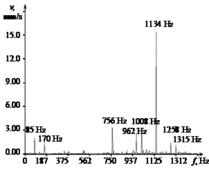
Fig. 6.Spectrum of the reducer bearing vibrations measured vertically. The gap in the bearing is increased, VRMS =11.6 mm/s
The spectral analysis of vibrations of the centrifugal compressor and reducer supports is presented as typical for this machine. Two cases are analysed: when the gap in a compressor sliding bearing is normal (0.2 – 0.3 mm, Figs. 5 and 7) and when the gap is increased (0.5 – 0.7 mm, Figs. 6 and 8). Here, spectral components of 50 Hz, 85 Hz and 126 Hz show the rotary speed of an electric motor, a turbine - axial compressor and a centrifugal compressor. The amplitudes of these components indicate the influence of either rotor unbalances or deviations of rotor centering. The component of 170 Hz presents a second harmonic of the turbine - axial compressor rotary frequency caused by anisotropy of the rotor structure. High frequency components of 1007 Hz, 1134 Hz and 1260 Hz are caused by the defects of the reducer gearwheels and their assembling.
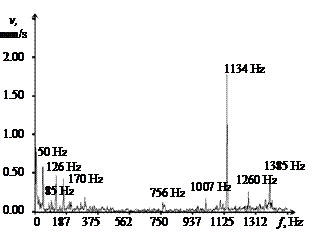
Fig. 7. Spectrum of the centrifugal compressor’s bearing vibrations
measured in the vertical direction.
Exploitation conditions are in a
regular range, VRMS =2.6 mm/s
It is obvious that the changes of bearing gaps and other parameters of certain machine elements influence vibration activity of other elements (reducer, turbine and electro motor) greatly. For example, in case when the gap in the compressor bearing is increased, the vibrations of the reducer bearing increase badly and VRMS (mean square value of vibrations speed) reaches the value of 11.6 mm/s. The component of 1134 Hz is specifically sensitive to the operating conditions of the reducer. An increase in a radial gap in a reducer sliding bearing causes an increase in this spectrum component amplitude by 2.5 times (Fig. 5) The analysis shows that such increase in this vibrations harmonic is caused by the changes in gearing conditions of reducers chevron gearwheels because of an increase in radial gaps in bearings. In such case the machine can not be operated and should be stopped for maintenance.
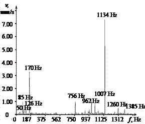
Fig. 8. Spectrum of the centrifugal compressor’s bearing vibrations measured in the vertical direction: a - exploitation conditions are in a regular range, b - gap in the bearing is increased, VRMS =6.3 mm/s
However, these data obtained experimentally when measuring the vibrations of bearing supports do not always suffice. For example, for comprehensive evaluation of rotary machine dynamic conditions it is also important to know the situation of rotor middle points (between supports) vibrations, because frequently there are the peak amplitudes of vibrations there. Often it is impossible (alike in the analysed case) to measure those vibrations experimentally, because the access to the inner elements is impossible during machine ch information can be obtained only by applying modelling of complicated dynamical situations [1, 2].
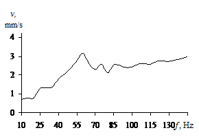
Fig. 9. Amplitude - frequency characteristic of the 4th element vibrations
Applied modelling of rotors dynamics yields the amplitude-frequency characteristics of various elements. The amplitude-frequency characteristic of the compressor rotor central element (4th element) and the reducer rotor central element (15th element) are presented in Figs. 9-11. It has been assumed that vibrations are generated by rotor unbalances.
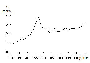
Fig. 10. Amplitude - frequency characteristic of the 15th element vibrations
These graphs give the information about the dynamic condition of certain rotor elements and can be obtained for any element, described in the numerical model. The peaks of presented curves show harmonics of the first critical speed.
Such modelling is also used to determine the sources of vibrations components measured experimentally. Therefore, such research helps find critical frequencies determining the influences of various defects and their critical values, etc. It helps predict both the machine vibration activity under certain conditions and reliability of this machine during its exploitation.
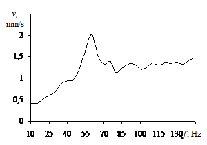
Fig. 11. Amplitude - frequency characteristic of t the centrifugal compressor’s bearing vibrations in the vertical direction
Results and conclusions. Research on complex rotary system vibration activity, based on the analysis of dynamic processes and the spectrum of vibrations used together with numerical modelling of dynamic situations and allow a thorough evaluation of machine dynamic condition and predict reliability of such equipment during its exploitation.
The analysis of experimental results makes it possible to evaluate the vibrations level for different harmonics and diagnose their sources, however it is not enough for the comprehensive analysis of machine dynamic condition.
Numerical modelling of dynamic processes in rotary systems gives very important information about the condition of various rotors elements (including those whose vibrations can not be measured experimentally).
References
1. Muszynska, A. Rotordynamics.- Boca Raton etc.: CRC Press, Taylor& Francis, 2005. -1128p.
2. Juzenas E., Juzenas K., Jonusas R., Barzdaitis V. Analysis of flexible rotor dynamic model adequacy applying FEM and various methods of damping evaluation. DSTA 2005- 8th Conference on Dynamical Systems: Theory and Applications, Lodz: 2005, volume 2, p.687-694
3. Royzman, V., Bohorosh, A. Dynamic characteristics identification of aircraft engine by method of trial parameters.- Mechanika, 3(53), 2005, p.34-38.
4. Zienkievicz O. C., Taylor R. L The finite element method. - Butterworth-Heinemann, 2000, vol. 2, 631 p.
5. Jonusas R., Juzenas E. The Investigation of Steam Turbine Flexible Rotor Vibrations by Means of FEM. In Proc. of 11th World Congress on Mechanisms and Machine Science, China Machine Press 2004, volume 5, p.2143-2147
6. Less, A. W., Sinha, J. K., Friswell, M. I. Model-based identification of rotating machines.- Mechanical Systems and Signal Processing.- 2009, No.23, p.1884-1893.
7. Bachschmid, N., Pennacchi, P., Chatterton, S., Ricci, R. On model updating of turbo-generator sets.- Journal of Vibroengineering.- 2009, Vol.11, No.3, p.379-391.
