

Партнерка на США и Канаду по недвижимости, выплаты в крипто
- 30% recurring commission
- Выплаты в USDT
- Вывод каждую неделю
- Комиссия до 5 лет за каждого referral
Design of an Aerial Lift Transportation System
September 24, 2009
Homework # 2
Brian Huff
Ray Jurek
James Potter
Charlie Simons
Task 1 – Identify the Decision Situation
- Application Domain: Aerial Lift Transportation Systems
Whether for recreation or out of necessity, aerial lift transportation systems provide a valuable asset to many mountainous regions. These lifts must safely and economically lift people and goods up massive expanses and through drastic changes in altitude. Lifts come in many different shapes and sizes depending on the specific needs of the operators. The inherent complexity involved in the design of ski lifts and the numerous types of ski lifts available to a designer requires a difficult set of decisions to be made. Although uncertainties might exist before any type of decision is made, the best decision possible must be reached to achieve profitability and safety goals. Since a ski lift design decision is such an expensive and complicated problem to solve, the use of system simulations can greatly aid in the decision process since physical tests and experiments tend to be too costly and time consuming to be beneficial.
- Describe the system
The system being considered for this simulation-design is known as an aerial lift. These lifts are crucial for transporting people up and down the side of mountain ranges. This design intends to look at closed cabin type lifts. A closed cabin should enable for a higher total passenger capacity while maximizing passenger comfort during the transportation process. A cable is suspended between towers and is strung along the entire length of the lift system. Motors located at the top and bottom of the lift elevation work to pull the cable and corresponding cabins up and down the mountain. While the cabins should move as quickly as possible from beginning to end, safety and comfort considerations must be taken into account to ensure the ride remains comfortable for the passengers. This design decision becomes a mechanical, statics, and inertial issue which must be addressed.
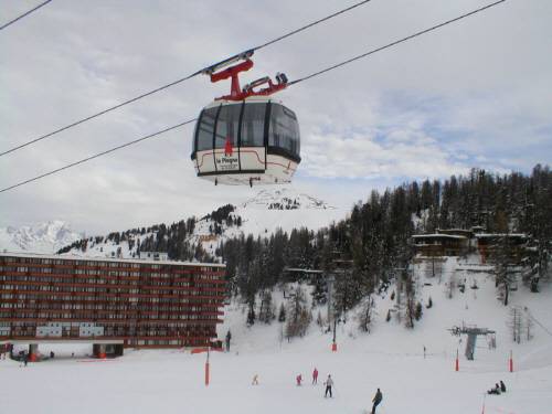
Figure 1 – Example Ski Lift System
(ref: http://en. wikipedia. org/wiki/File:Furniplagne_s. JPG)
Figure 1 above shows a typical closed cabin ski lift system similar to the one to be evaluated in this design study.
- Describe the Specific Design Decision
The specific design decision being considered for this project involves determining the cable size of the rope which will provide for the maximum amount of safety while also minimizing cost of both the initial construction and operation as well as maximizing the operating capacity of the ski lift. The final utility of the system will involve evaluating the overall profitability of the system over a period of 8 years. A specified motor will be chosen and this will remain a constant throughout the decision process. Different distances between support towers will be evaluated as well as varying cabin sizes in order to achieve the desired goals. The support cable will need to be evaluated for the tension and stresses experienced within the cable for different materials and thicknesses in order to determine the optimal configuration.
- Verify if the decision scenario is scoped within authority of the decision maker.
The decision scenario involves a mechanical system and the accompanying static and structural effects encountered as a result of different design decisions. As a result an engineer with familiarity regarding mechanical systems and/or structural analysis would have the authority to help make the decision.
Task 2: Determine an Objectives Hierarchy
A fundamental objective hierarchy was created in order to discover the design objectives of the project. The main objectives were to maximize the safety of the lift for the riders and maximize the profit of the lift for the owner. The objective of maximizing safety breaks down into minimizing the failure of the lift cable, minimizing the injuries of the lift riders, and minimizing the loss of life for the lift riders. The objective of minimizing the cost breaks down into the two subcategories of maximizing the utilization and minimizing the initial cost of the lift. Maximizing the utilization can be further decomposed into minimizing the lift time and maximizing the capacity of the lift. Minimizing the initial cost breaks down into minimizing the lift cable diameter and maximizing the post distances of the posts used to support the cable.
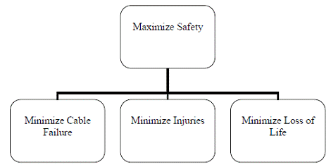
Figure 2: Maximize Safety Objective Hierarchy:
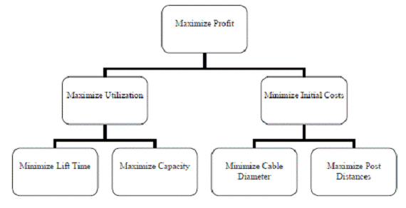
Figure 3: Maximize Profit Objective Hierarchy
A means objective diagram was created in order to determine how to implement the fundamental objectives in Figures 2 and 3. All of the means objectives shown below in Figure 4 work together to achieve the main objective, which is to create a cost effective lift.
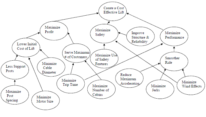
Figure 4: Means Objective Hierarchy Diagram
All of the objectives shown above in Figure 4 are important to achieving a cost effective lift but the main objectives that will be focused upon in this project are shown below in Table 1 along with their attributes. Dymola will be used to model the forces upon the cable with different variations of the attributes listed below. Some of the objectives that can not be modeled within Dymola will be modeled within Excel.
Objective | Attribute |
Larger Post Spacing | Post Distance |
Minimize Motor Size | Motor Power Output |
Minimize Cable Diameter | Cable Diameter, Ability to Handle Load |
Minimize Trip Time | Trip Time |
Maximize Number of Cabins | Amount of Cabins, Force added to Cable |
Minimize Wind Resistance | Forces on Cable Due to Wind |
Table 1 - Objective and Attribute Relations
Task 3: Identify the Design Alternatives
The design alternatives that we will consider in this project will focus around the utility of profit after 8 years. In order to achieve this profit, aspects of the design will need to tailor to minimizing costs as well as ensuring safety of the overall system. The various parameters which will most directly affect the system are the following:
- Number of Cabin Cars Size of Cabin Cars Diameter of Cable Power of System Motor
These aspects will have the greatest impact on the results of the system. There are some important decisions that will be made in accordance with these selections as well though. For example, the selection of the cable diameter will be associated with an initial material assumption. Using this framework, we can then manipulate the diameter of the cable for various materials which will allow us to gain a variety of material properties and face various costs associated with each material. Initially though, the material will be defined as a known factor with the construction of the cable being assumed as a custom diameter to our specification. Aspects of the cabin size and the weight as well as the power of the motor will be limited to selections of open market units. This will help us to limit the number of decisions and variables for these alternatives while limiting the cost of creating a new custom solution.
One other main decision element is the number of cable support structures along the path of the lift system. To simplify calculations, we will set an initial value for this distance as an estimate. Once we determine the relationship of our cable with this distance, we could vary the distance between posts to further optimize the cost; however, we will try to maintain the distance without alternation in order to keep the focus on the decision of the four variables previously listed. This assumption of a rigid constraint on the distance between support structures is certainly realistic in practice where an elevated path may only offer a limited number of positions that these posts may be placed without significant construction work.
Task 4: Identify the Structure of the Design Problem
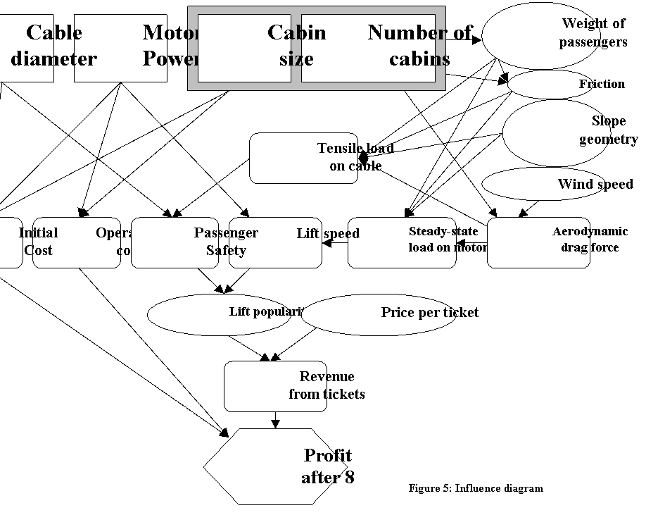
The structure of the design problem is represented by the influence diagram in Figure 5. The lower part of the diagram will be explained first, since discussion of the upper-level blocks in the diagram will often reference calculations that directly influence utility, and other lower-level blocks. Block names are shown in underlined bold letters.
· Profit after 8 years is chosen as the utility. It is influenced by three main factors:
o Initial cost is the cost of all parts and equipment needed to build the lift. The cost is only paid once. An increase in initial cost decreases utility.
o Operating cost is the cost of processes required to operate the lift. This includes the cost of electrical power used by the motor (determined by motor power), and miscellaneous repairs and maintenance (influenced by the cabin size and number of cabins). This cost is paid over time, as opposed to the single-lumped-sum initial cost. Like the initial cost, an increase in operating cost decreases utility.
o Revenue from tickets is the income generated whenever a passenger purchases a ticket to ride the lift. This is the only source of income for the lift that will be considered. An increase in revenue from tickets will increase utility. The revenue from tickets is a function of lift popularity (the number of people who buy tickets), and the price per ticket. The price per ticket is shown as a chance event because there is not adequate space on the diagram to show all of the block’s possible contributing factors.
Now that the lower part has been discussed, the rest of the diagram can be explained from the top-down. The designer first specifies four main design variables:
· Cable diameter influences the initial cost and passenger safety. Passenger safety is determined by the strength of the cable relative to the tensile load on cable, which will be discussed shortly. Passenger safety will affect the lift popularity.
· Motor power, which influences the initial cost, operating cost, and lift speed. Lift speed is calculated by comparing the motor power to the steady-state load on motor.
· Cabin size and number of cabins generally have the same influence on subsequent blocks, so they are shown inside a single combined-decision block. They both affect the initial cost and operating cost. Larger cabins and a greater number of cabins will tend to increase the initial cost (larger/more equipment requires more money to purchase), and the operating cost (more cabins will increase the amount of maintenance, and larger cabins may require more expensive parts for repairs). The tensile load on cable and the steady-state load on motor are influenced mainly by the slope geometry (vertical rise, horizontal travel, etc.), and by the following blocks, each of which is influenced by the cabin size and number of cabins:
o Weight of passengers. This block is a random chance instead of a calculation because it is not known how many passengers will be riding up (or down) the lift at any given time. While the cabin size and number of cabins do not explicitly determine the weight of the passengers, they do place an upper limit on the possible number of passengers, which in effect puts an upper limit on the weight of the passengers.
o Friction, which must be overcome by the motor, will tend to increase with an increase in the weight of the suspended system. It is therefore affected by the cabin size, number of cabins, and the weight of passengers.
o Aerodynamic drag force is a function of the frontal area (determined by the quantity and size of the cabins), and the wind speed. Aerodynamic drag can also have large dynamic effects if the wind blows at an excitation frequency of the lift. To study the wind’s dynamic effects, aerodynamic drag will be simulated in Dymola.
Task 5: Identify the Simulation Scenario for an Energy-Based System Model
The design objective which will require an energy based model will be the objective to maximize safety of the system. While the results of the system allow for descriptions of the cost of the project as well as the ultimate operating capacity, a dynamic model needs to be created to judge failure of the cable which is the ultimate goal of safety. This model will also help us to understand the implications that wind and motor size will have on the safety of the cable.
In the third homework assignment, we will approach the design of the cable in the system. This will allow us to begin to understand the behavior of the cable under various cart weights. To simplify the system, we will look at the cable between only one pair of support structures on the path of the cable. This will allow us to develop a simple model of the cable and to determine it's response. To pull on the cable we will implement a varying force on one end of the cable segment and consider the other end fixed. This will allow us to gauge a dynamic response of the cable to the motor's varying the cable diameter and assessing the tensile forces in the cable, we can then verify what materials (if any) will be able to meet those strength requirements and the associated safety factor.
This system will be mainly in the physical domain operating on the cable, fixed support structures of the cable system which the cable is strung between, and passenger cars which will have a fixed weight which will have a varying increase in force on the cable due to the aerodynamics of the cable and a varying wind speed which will be modeled in HW 4. There will be a simple motor modeled in the electrical domain which will help us to determine the requirements on the motor to operate the cable system as well as to implement a test cycle of motor operation which will provide an estimate of the electrical operation costs to power the lift. This varying operational cycle of the motor will be the same varying force on the cable to assess failure of the system.
To simplify the solution of the system, we will abstract that the relationship of the stress in the cable between a single set of support towers will be no different than a span of the cable between any other two towers. We will also assume that there will be a constant friction loss of the system (possibly zero) which represents the entire system friction of the rotational supports which allow the cable to pass over the support towers and around the motor pulleys at each end of the system. The model will also assume that a cable can be modeled as many segments of rigid bodies connected to one another (similar to a chain with multiple links). Initially we will also consider that no other forces will act on the cable besides the motor tension, the cable car weights, and the support structures' normal forces. Other possible forces would typically include birds resting on the cable, rust weakening the cable, possible avalanche on the mountain, and many other possibilities. From the analysis of the system for dynamic safety, this will provide our decision maker with the ability to optimize each decision while knowing the effects on the safety of the system as a whole.
Task 6: Assess your Plan
There are a number of aspects of this project which represent a significant deal of uncertainty. Although not all of the potential pitfalls involved in this design project can be known at the outset, some potential stumbling blocks can be identified:
- Modeling the linkage for the cable properly – As stated in Task 5, the modeling of the cable linkages requires a significant amount of assumptions and simplifications to be made. Creating a Modelica model in which the cable behaves as it should while being suspended on both ends presents a difficult and unique challenge. The cable will be modeled as separate links of a chain and ensuring the individual links all behave as a singular unit while suspended in the air. The proper dampening and stiffness for the individual links needs to be determined but will vary depending on the thickness of cable used. Simulation runtime – The simulation model will create the cable using many smaller segments. Adding more and more segments to the model will drastically increase the simulation runtime. If the simulation runtime becomes too large, then the simulation itself is no longer an efficient tool for use in the design decision. On the other hand, if not enough cable segments are used, the cable may not behave properly. If the model does become too unwieldy for simulation then fewer cable segments will be used in an attempt to model the design solution. Factoring in Unknowns – This design problem requires many assumptions to be made covering a range of topics. From the weight of the cabins and the cable itself and how that weight is distributed, to the potential for drastically changing weather phenomena found on most mountain sides, these unknowns require quantification if they are to be included within the decision process. Dealing with too many unknowns runs the risk of breaching the scope of the project or creating a problem which is simply too complex to solve. If these unknowns become too much of an issue, great care must be take to eliminate some of the variables (such as the anticipated maximum wind speed seen by the passenger cabin) in order to reach a more appropriate design situation.
Task 7: Articulate your Learning Objectives:
Brian Huff:
Every engineering application requires multiple decisions to be made. These decisions must often times be made very quickly and often using incomplete or inadequate data. My intent is to learn how to become a better decision make and further explore the intricacies involved in making engineering decisions. I also wish to learn more about how a decision made in the past effects future decisions and how everything becomes tied together. I have no prior experience with Dymola and feel that I will greatly benefit from the opportunity to learn another piece of engineering software.
James Potter:
My main goals for this course will be the following:
Learn about the systems-design process. I worked as a product designer for a year, and I saw first-hand how important it is to adequately define the problem before getting to work, especially if multiple people or departments are trying to work concurrently. Many man-hours were lost because of confusion and miscommunication. I would like to learn techniques for organizing a large set of design specifications into a compact form that can be more easily visualized.
Become competent with the Dymola software, and hopefully use it in my research. My PhD thesis topic will likely involve the modeling and control of construction cranes, which lend themselves well to computer simulation. My research lab currently uses MATLAB and Simulink for crane simulations. While MATLAB is extremely powerful and useful for some applications, it seems like Dymola is much better-suited for this kind of problem. As a Dymola novice, it took me 2 hours to make a crane model that would have taken several days (if not weeks) to replicate in MATLAB.
Ray Jurek:
I am interested in the design of mechanical systems and through this course I would like to learn the proper modeling and simulation techniques of these systems. I feel that learning the Dymola modeling and simulation software will be a great design tool to have. I also hope to gain knowledge on how to properly follow the many steps of the design process when creating a product or working on a project. I feel that by learning the material in this course I will be able to be a great asset to design groups in the future.
Charlie Simons:
Through the course of this project, I am most interested in learning the methods of decision analysis using basic modeling. While I am currently working part time in industry, I see the benefits of effective decision making on a daily basis and want to increase this skill. Effective modeling holds only limited utilization in my current work environment and I believe that by working through this project, I will be able to gain a better perspective of the scope of which I can effectively use basic modeling in my job. I am not interested in becoming an expert at Dymola although I am interested in exploring it's use beyond this course. Ultimately, my main objective in this project and course overall is to improve my skills as a project engineer in order to make more effectively supported decisions in a speedy and presentable manner.
