
Партнерка на США и Канаду по недвижимости, выплаты в крипто
- 30% recurring commission
- Выплаты в USDT
- Вывод каждую неделю
- Комиссия до 5 лет за каждого referral
Самостоятельное устройство ENERGY
Изобретение представляет собой устройство, как самодостаточный (само питание) и производство готовых к использованию электрической энергии, начинает действовать с начальной электрической энергии, полученной от аккумулятора или подобного источника энергии, передачи магнитного поля, создаваемого в первой катушки на второй катушке через стабилизатор частоты, после того, как ритмично стабилизации магнитного поля произошла между катушками, преобразует независимый энергии получила второй бобины из воздуха в электрическую энергию.
Сегодня электрической энергии могут быть получены с помощью различных технологий. Для того, чтобы подвести некоторые из них, электрической энергии могут быть получены через плотины, от движения волн, атомные электростанции, с помощью солнечной энергии, топлива, гидроэлектростанций и приравненных к ним местностях за счет использования различных технологий. Существуют различные преимущества и недостатки, среди этих различных методов, используемых для генерации электрической энергии. Общая цель всех этих методов для получения энергии дешевле и быстрее, обеспечивая высокую эффективность.
Настоящее изобретение улучшено за счет использования различных технологий на сегодняшний день менее затратным способом и без ущерба для природы, и с помощью совершенно другой техники из приведенного выше упоминается (в настоящее время методов, используемых сегодня).
Настоящее изобретение получает энергию внешне только на первый начальной стадии. Это упоминается энергия может быть легко создается из небольшого аккумулятора или аккумуляторные батареи или подобных источников. 1 -2 секунд после запуска устройства, выключатель питания на энергетическом входе устройство отсекает внешние электрические (от аккумулятора или подобного источника энергии) с путем создания электрической энергии. Очень немногие части этой электрической энергии, вырабатываемой используется устройство, чтобы накормить себя и большую часть сбрасывается готов к использованию. Пока устройство не выключается или нет проблема возникла внутри, устройство производит энергию постоянно. В последние технологии, нет устройства, подобного изобретения производить энергию постоянно, подавая себя.
Для того, чтобы поддерживать устройство для генерации электрической энергии последовательно, две схемы разработаны внутри устройства.
Первая схема, состоит из реле времени реле, конденсаторы, указывает, высокая частота генератора, первого фильтра, сначала катушку, первый регулятор частоты (эта схема отображается жирная линия на рисунке) второго контура, состоит из второго фильтра, стабилизатор частоты, второй катушке, второй регулятор частоты.
Первая схема предназначена для производства электроэнергии путем передачи электро магнитного поля произошла на первом катушка с электрической энергией, полученной от независимого начального электропитания, ко второй катушке. А в качестве второго контура; В связи с сильным магнитным полем, полученных от первого бобины, возникает магнитное поле разница между катушками. Магнитное поле произошла разница между второй и первой бобины катушки стабилизированный при помощи стабилизатором частоты в этой цепи линии. Как стабилизации магнитного поля различие помощью стабилизатора частоты, эта схема линии также преобразует энергию, которая движется самостоятельно в воздух во второй катушке разработан в рамках этой линии в электрическую энергию. Эта электрическая энергия образуется второй катушке регулирует необходимую частоту (220 В - 50 Гц или 110 В - 60 Гц) для использования, при помощи второго регулятора частоты предназначены на бобину производства. Этот сгенерированный электрическая энергия передается в район предполагаемого использования через точки выхода. Через цепь кабели, подключенные к выходу точки, устройство питается с созданного электрической энергии. Это упомянутый процесс eventuates 1 -2 секунд после того, устройства получили работу. После этого процесса, власти Реле времени предназначены переключатель на входе в устройство вышло из начальной энергоснабжения. После этого этапа, устройство генерирует энергию самостоятельно.
Изобретение предназначено как однофазные и как номер фазы желательно быть увеличен, катушка номер должен быть увеличен на каждом этапе. В зависимости от количества катушек, потенциал других деталей, используемых в устройстве увеличивается симметрично.
можно получать энергию в необходимом количестве KW с устройства. Необходимо увеличить пропускную способность части в зависимости от стоимости электроэнергии. Цифры, связанные с изобретением даны закрытые, с соответствующими цифрами:
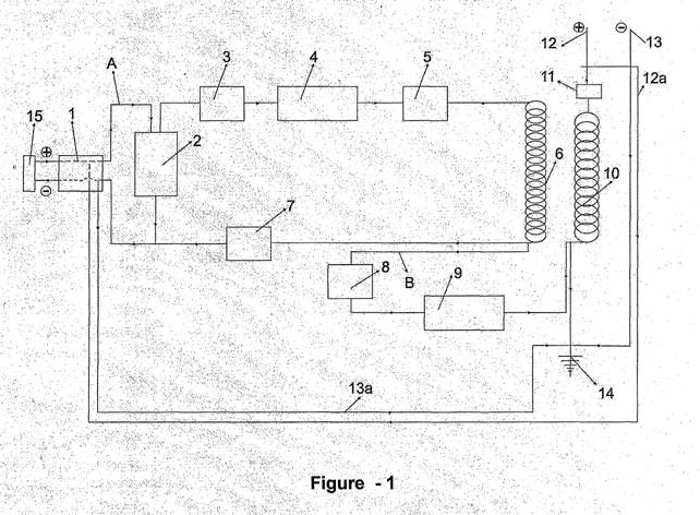
Рисунок 1 - Схема изобретения
части, относящейся к изобретению приведены цифры и объяснения отвечать эти цифры следующим образом:
1 - выключатель
2 - конденсатор
3 - очки (как дистрибьютор двигателя) 4 - Высокочастотный генератор
5 - Первый фильтр
6 - Первая катушка
7 - первый регулятор частоты
8 - Второй фильтр
9 - стабилизатор частоты (регулятор)
10 - вторая катушка
11 - Второй регулятор частоты
12 - Exit (фаза) (положительный)
12a-положительных преобразований кабель
13 - Выход (нейтральный)
13-отрицательные преобразования кабель
14 - нейтральный (заземление)
15 - Начальная питания
Первого схема кабеля
B-Вторая схема кабеля
действия настоящей Устройство объясняется, как показано ниже, давая ссылки на номера деталей через фигуру прилагается.
энергии и частоты контура на первом контуре (А)
Открытие выключатель питания, пользователь дает электрической энергии, полученной от начальной энергии (15) Первый кабель цепи (А). Будучи загружена с электрической энергией, полученной от источника энергии (15), конденсатор (2) выступает в качестве насосов, а также предоставляет точки (3) давать электрический высокой частоты генератора (4). Высокочастотный генератор (4) передается большое количество частот она создается для первого фильтра (5). Первый фильтр (5) стабилизирует частоты, полученные от высокочастотного генератора (4) и регулярно передает в первую катушку (6). Создание магнитного поля вокруг себя с высокой частотой регулярно получал от первого фильтра (5), первый катушка (6), передает его на второй катушки (10). Впоследствии, после первого кабеля цепи (А), высокие частоты при переходе от первой катушки (6) переходит в первый регулятор частоты (7). Первый регулятор частоты (7) стабилизирует получили высокие частоты в соответствии с необходимостью и устраивает, не причинив никакого вреда частям на выходе.
Энергия и частота замыкания на второй цепи (B)
высокочастотных повышалось от первой катушки (6) поступает на второй фильтр второго контура (B). Второй фильтр (8), передает частоты, полученные от первой катушки (6) стабилизатор частоты (9). Электромагнитные поля произошла на катушках (6, 10) различны и магнитного поля на первой катушки (6) выше, чем вторая катушка (10). На этом этапе стабилизатор частоты (9) стабилизирует различных электромагнитных полей произошло в первой и второй катушки (6, 10). Это стабилизированный высокой частоте выхода из второй катушки (10) и с учетом необходимой (необходимых для использования) частота степени при помощи второго регулятора частоты (11). Пользователь использует электрическую энергию, в устройстве при помощи выхода (фаза) (положительный) (12) и выход (нейтральное) Кабель (13). Положительный кабель преобразования (12а) на выходе из устройства и отрицательный кабель преобразования (13) связаны с выключателем питания. 1-2 секунды после того, устройство начинает генерировать электрический, электрический энергии, вырабатываемой передается на питание (1) с помощью положительный кабель преобразования (12а) и отрицательный кабель преобразования (13а). Реле времени на питание (1) нарушает энергии, полученной от первоначального источника питания (15). После этого этапа, устройство продолжает генерировать электроэнергию кормление себя самостоятельно вырабатываемой энергии и самостоятельно, без зависимости от любой энергии извне. Устройство продолжает генерировать неограниченное количество энергии, если она не закрыта через выключатель питания (1) или не возникла проблема в системе.
ПРЕТЕНЗИИ
1 - самостоятельное устройство энергией, начиная работать с начальной электрической энергии, полученной от независимого начального источника питания (15), передачу электро магнитного поля произошла на первом катушка (6) на второй катушки (10), стабилизации магнитного поле произошла между катушками (6, 10) с помощью стабилизатор частоты (9), после преобразования независимой энергии, получаемой из воздуха вторую катушку (10) в электрическую энергию, и само питание и создания готовых к использованию электрической энергии, состоит из следующих частей, выключатель питания (1), конденсатор (2), точки (3), высокочастотный генератор (4), первый фильтр (5), первая катушка (6), первый регулятор частоты (7), второй фильтр (8), стабилизатор частоты (регулятор) (9), второй катушки (10), второго регулятора частоты (11), Exit (фазы)
(Положительный) (12), положительный кабель питания самостоятельно (12а), выход (нейтральное) (13), отрицательный кабель питания самостоятельно (13а), нейтральный (заземление) (14), первоначальный источник питания (15).
2 - независимых энергии устройство по п.1, характеризуется включить конденсатор (2) для передачи электрической получил от первоначального источника питания (15) очков (3).
3 - самостоятельное устройство энергии по п.1, характеризуется включить пункты (3) передавать частоты, высокочастотный генератор (4) потребности.
4 -. самостоятельное устройство энергии по п.1, характеризуется включить высокочастотный генератор (4) для передачи высоких частот происходит в себе на первый фильтр (5)
5 - самостоятельное устройство энергии по п.1, характеризуется включить первый фильтр (5), чтобы заказать частоты, полученные от высокочастотного генератора (4) и передать первую катушку (6).
6 - самостоятельное устройство энергии по п.1 которой характеризуется включить первую катушку (5), обеспечивая высокую электро магнитное поле вокруг себя для передачи высоких и регулярной частотой, полученной от первого фильтра (5), на второй катушки (10) и электрической энергии, полученной от начальной мощности питания (15) и к первому кабелю цепи (А) и второй кабель цепи (B).
7 - самостоятельное устройство энергии по п.1, характеризуется для относятся прежде регулятора частоты (7) для стабилизации нормальной частоты, полученные от начальный источник питания (15) с высокой частотой, полученной от первой катушки (6).
8 - самостоятельное устройство энергии по п.1, характеризуется включить второй фильтр (8), чтобы заказать высокой частоты, полученные от первых катушка (6) и передать частоты стабилизатора (регулятора) (9).
9 - независимый энергии Устройство по п.1, характеризуется частотой включения стабилизатора (регулятора) (9) для стабилизации электромагнитных полей различий произошло между первой катушки (6) и второй катушки (10).
10 - самостоятельное устройство энергии по п.1, характеризуется в включить вторую катушку (10) для выработки электроэнергии сочетание электро магнитного поля, полученные от первой катушки (6) и независимой энергии, получаемой из воздуха, после того, как стабилизатор частоты (регулятор) (9) заказов электромагнитные поля между бобин
(6, 10).
H-независимое устройство энергии по п.1, характеризуется включить второй регулятор частоты (11) для стабилизации высоких частот, полученных от второй катушки (10) в соответствии с необходимостью использовать.
12 - самостоятельное устройство энергии по п.1, характеризуется включить выход (фаза) (положительный) (12) и Exit (нейтральный) (13) предназначены для того, чтобы устройство использовать электрическую энергию,.
13-независимое устройство энергии п.1, в которой характеризуется включить положительный кабель преобразования (12а) и отрицательный кабель преобразования (13а), предназначенный для того, чтобы включить устройство, чтобы накормить себя с электрической энергии, вырабатываемой.
14-независимое устройство энергии по п.1, характеризуется включить начальное питания (15), чтобы обеспечить устройство работает в первый раз.
o. публикации: |
| WO/2008/103129 | No. международной заявки: |
| PCT/TR2007/000050 | |
Дата публикации: | 28.08.2008 | Дата международной подачи: | 08.06.2007 | |||
Требования в соответствии с Главой 2 подано: | 19.12.2008 |
МПК: H02M 11/00 (2006.01), H02N 11/00 (2006.01) Заявители: KAPANADZE, Tariel [GE/GE]; (GE).
TURK, Metin [TR/TR]; (TR) (For All Designated States Except US) Изобретатели: KAPANADZE, Tariel; (GE) Агент: YALCINER, Ugur G. (YALCINER DANISMANLIK VE DIS TICARET LTD. STI.); Tunus Caddesi No:85/8, Kavaklidere, 06680 Ankara (TR) Дата приоритета:
u 2007/00996 | 20.02.2007 | TR |
Название (EN) INDEPENDENT ENERGY DEVICE
(FR) DISPOSITIF AUTONOME DE PRODUCTION D'ÉNERGIE
Реферат:![]()
(EN)The independent energy device improved with this invention, starts operation with the initial electric energy received from the initial energy supply (15) and afterwards generates energy consistently and is characterized to include power switch (1), capacitor (2), points (3), high frequency generator (4), first filter (5), first bobbin (6), first frequency adjuster (7), second filter (8), frequency stabilizer (adjuster) (9), second bobbin (10), second frequency adjuster (11), exit (phase) (positive) (12), positive self feeding cable (12a), exit (neutral) (13), negative self feeding cable (13a), neutral (grounding) (14), initial power supply (15).
(FR)L'invention concerne un dispositif de production d'énergie autonome amélioré, qui commence à fonctionner à l'aide de l'énergie électrique initiale provenant d'un système d'alimentation en énergie (15) initial, et produit ensuite de l'énergie de manière stable. Le dispositif est caractérisé en ce qu'il comprend un commutateur de puissance (1), un condensateur (2), des points (3), un générateur haute fréquence (4), un premier filtre (5), une première bobine (6), un premier moyen de réglage de la fréquence (7), un second filtre (8), un moyen de stabilisation (réglage) de la fréquence (9), une seconde bobine (10), un second moyen de réglage de la fréquence (11), une sortie (phase) (positive) (12), un câble d'autoalimentation positif (12a), une sortie (neutre) (13), un câble d'autoalimentation négatif (13a), un conducteur neutre (mise à la terre) (14) et une alimentation électrique initiale (15).
Указанные государства: AE, AG, AL, AM, AT, AU, AZ, BA, BB, BG, BH, BR, BW, BY, BZ, CA, CH, CN, CO, CR, CU, CZ, DE, DK, DM, DO, DZ, EC, EE, EG, ES, FI, GB, GD, GE, GH, GM, GT, HN, HR, HU, ID, IL, IN, IS, JP, KE, KG, KM, KN, KP, KR, KZ, LA, LC, LK, LR, LS, LT, LU, LY, MA, MD, ME, MG, MK, MN, MW, MX, MY, MZ, NA, NG, NI, NO, NZ, OM, PG, PH, PL, PT, RO, RS, RU, SC, SD, SE, SG, SK, SL, SM, SV, SY, TJ, TM, TN, TR, TT, TZ, UA, UG, US, UZ, VC, VN, ZA, ZM, ZW.
African Regional Intellectual Property Org. (ARIPO) (BW, GH, GM, KE, LS, MW, MZ, NA, SD, SL, SZ, TZ, UG, ZM, ZW)
Eurasian Patent Organization (EAPO) (AM, AZ, BY, KG, KZ, MD, RU, TJ, TM)
European Patent Office (EPO) (AT, BE, BG, CH, CY, CZ, DE, DK, EE, ES, FI, FR, GB, GR, HU, IE, IS, IT, LT, LU, LV, MC, MT, NL, PL, PT, RO, SE, SI, SK, TR)
African Intellectual Property Organization (OAPI) (BF, BJ, CF, CG, CI, CM, GA, GN, GQ, GW, ML, MR, NE, SN, TD, TG).
INDEPENDENT ENERGY DEVICE
The present invention is a device both self sufficient (self feeding) and producing ready to use electric energy, starts to operate with the initial electrical energy received from accumulator or similar source of energy, transferring the magnetic field generated in first bobbin to second bobbin through a frequency stabilizer, after rhythmically stabilizing the magnetic field occurred between the bobbins; converts the independent energy - received by the second bobbin from the air - to electric energy.
Today electric energy can be generated by using various kinds of technologies. In order to summarize some of them; electric energy can be generated through dams, from the motion of waves, by nuclear power plants, by using solar energy, fuel oil, hydroelectric power plants and similar areas through using various technologies. There are different advantages and disadvantages among these various techniques used for generating electric energy. The general purpose of all these techniques is to generate energy cheaper and faster by providing high efficiency.
The present invention is improved through using different technologies of today, by less costly way and without harming the nature, and using a very different technique from the above mentioned (present techniques used today).
The present invention receives energy externally only at first starting phase. This mentioned energy can be easily generated from a small accumulator or chargeable battery or similar sources. 1 -2 seconds after the device is started, the power switch at the energy input of the device cuts the external electric (from accumulator or similar source of energy) off by generating electric energy. A very few part of this electric energy generated is used by the device to feed itself and the most part is discharged ready to be used. As long as the device is not shut down or no problem occurred inside, the device generates energy recent technology, there is no device similar to the present invention producing energy consistently by feeding itself.
In order to maintain the device to generate electric energy consistently, two circuits are designed inside the device.
First circuit; consists of time relay switch, capacitor, points, high frequency generator, first filter, first bobbin, first frequency adjuster (this circuit is displayed with bold line on the figure) Second circuit; consists of second filter, frequency stabilizer, second bobbin, second frequency adjuster.
First circuit is designed for generating electricity by transferring the electro magnetic field occurred at the first bobbin with the electric energy received from the independent initial power supply, to second bobbin. And as the second circuit; Due to the high magnetic field received from the first bobbin, there occurs a magnetic field difference between the bobbins. The magnetic field difference occurred between the second bobbin and first bobbin stabilized by the help of frequency stabilizer within this circuit line. As stabilizing the magnetic field difference by the help of frequency stabilizer, this circuit line also converts the energy which is moving independently in the air at the second bobbin designed within this line to electric energy. This electric energy formed by the second bobbin adjusts the necessary frequency (220 V - 50 Hz or 110 V - 60 Hz) for use, by the help of second frequency adjuster designed at the bobbin output. This generated electric energy is transferred to the intended usage area via exit points. Through the circuit cables connected to the exit points, the device feeds itself with the generated electric energy. This mentioned process eventuates 1 -2 seconds after the device is got started. After this process, the time relay power switch designed at the input of the device breaks the initial energy supply. After this stage, the device generates the energy independently.
The present invention is designed as single phase and as the phase number is desired to be increased, the bobbin number shall also be increased for each phase. Depending on the number of bobbins, the capacities of other parts used in the device are increased symmetrically.
It is possible to obtain energy in desired amounts of KW from the device. It is necessary to increase the capacity of the parts depending on the value of the electric energy. The figures related to the invention are given enclosed; from the related figures:
Figure 1- Schematic view of the present invention
The parts related to the invention are given numbers and the explanations responding these numbers are as follows:
1- Power switch
2 - Capacitor
3- Points (as distributor of an engine) 4- High frequency generator
5- First filter
6- First bobbin
7- First frequency adjuster
8- Second filter
9- Frequency stabilizer (adjuster)
10- Second bobbin
11- Second frequency adjuster
12- Exit (phase) (positive)
12a - Positive transformation cable
13- Exit (neutral)
13 a - Negative transformation cable
14- Neutral (grounding)
15 - Initial power supply
A - First circuit cable
B - Second circuit cable
The operation of the present device is explained as below, giving reference to the parts' numbers through the figure enclosed.
Energy and frequency circuit on the first circuit (A)
Opening the power switch, the user gives the electric energy received from the initial energy supply (15) to the first circuit cable (A). Being loaded with the electric energy received from the energy supply (15) the capacitor (2) serves as a pump, and provides the points (3) to give electric to the high frequency generator (4). High frequency generator (4) transfers the high amount of frequency it generated to the first filter (5). First filter (5) stabilizes the frequency received from the high frequency generator (4) and regularly transfers to the first bobbin (6). Creating a magnetic field around itself with the high frequency regularly received from the first filter (5); first bobbin (6) transfers it to the second bobbin (10). Subsequently, following the first circuit cable (A), the high frequency passing from the first bobbin (6) passes to the first frequency adjuster (7). The first frequency adjuster (7) stabilizes the received high frequency in accordance with the need and arranges without causing any harm to the parts at its exit.
Energy and frequency circuit on the second circuit (B)
The high frequency rised from the first bobbin (6) enters to the second filter through the second circuit (B). Second filter (8) transfers the frequency received from the first bobbin (6) to the frequency stabilizer (9). The electromagnetic fields occurred at the bobbins (6, 10) are different and the magnetic field at the first bobbin (6) is higher than the second bobbin (10). At this stage the frequency stabilizer (9) stabilizes the different electromagnetic fields occurred at the first and the second bobbins (6, 10). This stabilized high frequency exits from the second bobbin (10) and is adjusted for the required (necessary for the use) frequency degree by the help of the second frequency adjuster (11). The user uses the electric energy generated in the device by the help of exit (phase) (positive) (12) and exit (neutral) cable (13). The positive transformation cable (12a) at the exit of the device and the negative transformation cable (13 a) are connected to the power switch. 1-2 seconds after the device starts to generate electric, the electric energy generated is transmitted to the power switch (1) via positive transformation cable (12a) and negative transformation cable (13a). The time relay at the power switch (1) breaks the energy received from the initial power supply (15). After this stage, the device continues to generate electric energy feeding itself with the self generated energy and independently without depending to any energy from outside. The device continues to generate unlimited energy as long as it is not closed via the power switch (1) or no problem occurred within the system.
CLAIMS
1- An independent energy device, starting to operate with the initial electric energy received from the independent initial power supply (15), transferring the electro magnetic field occurred at the first bobbin (6) to second bobbin (10), stabilizing the magnetic field occurred between the bobbins (6, 10) with the help of frequency stabilizer (9), afterwards converting the independent energy received from the air by the second bobbin (10) to electric energy, both self feeding and generating ready to use electric energy; composed of following parts; power switch (1), capacitor (2), points (3), high frequency generator (4), first filter(5), first bobbin (6), first frequency adjuster (7), second filter (8), frequency stabilizer (adjuster) (9), second bobbin (10), second frequency adjuster (11), Exit (phase)
(positive) (12), positive self feeding cable (12a), exit (neutral) (13), negative self feeding cable (13a), neutral (grounding) (14), initial power supply (15).
2- An independent energy device of Claim 1 wherein characterized to include capacitor (2) to transfer the electric received from the initial power supply (15) to points (3).
3- An independent energy device of Claim 1 wherein characterized to include points (3) to transfer the frequency that the high frequency generator (4) needs.
4- An independent energy device of Claim 1 wherein characterized to include the high frequency generator (4) to transfer the high frequency occurred within itself to the first filter (5).
5- An independent energy device of Claim 1 wherein characterized to include the first filter (5) to order the frequency received from the high frequency generator (4) and transfer to the first bobbin (6).
6- An independent energy device of Claim 1 wherein characterized to include the first bobbin (5); providing a high electro magnetic field around itself to transfer the high and regular frequency received from the first filter (5) to the second bobbin (10) and the electric energy received from the initial power supply (15) both to the first circuit cable (A) and to the second circuit cable (B).
7- An independent energy device of Claim 1 wherein characterized to include first frequency adjuster (7) to stabilize the normal frequency received from the initial power supply (15) with the high frequency received from the first bobbin (6).
8- An independent energy device of Claim 1 wherein characterized to include the second filter (8) to order the high frequency received from the first bobbin (6) and transfer to the frequency stabilizer (adjuster) (9).
9- An independent energy device of Claim 1 wherein characterized to include frequency stabilizer (adjuster) (9) to stabilize the electro magnetic field differences occurred between the first bobbin (6) and second bobbin (10).
10- An independent energy device of Claim 1 wherein characterized to include the second bobbin (10) to generate electric energy combining the electro magnetic field received from the first bobbin (6) and the independent energy received from the air, after the frequency stabilizer (adjuster) (9) orders the electro magnetic field between the bobbins
(6, 10).
H-An independent energy device of Claim 1 wherein characterized to include the second frequency adjuster (11) to stabilize the high frequency received from the second bobbin (10) in accordance with the need to be used.
12- An independent energy device of Claim 1 wherein characterized to include Exit (phase) (positive) (12) and Exit (neutral) (13) designed in order to enable the device to use the electric energy generated.
13-An independent energy device of Claim 1 wherein characterized to include positive transformation cable (12a) and negative transformation cable (13a) designed in order to enable the device to feed itself with the electric energy generated.
14-An independent energy device of Claim 1 wherein characterized to include the initial power supply (15) to provide the device operates at the first time.
