

The article is published on materials of the report on “International Scientific Forum
Butlerov Heritage – 2015”. http://foundation. /bh-2015/
Submitted on April 29, 2015.
Development of the construction and method
of calculating the vortex devices for gas cleaning
© Vitaly G. Afanasenko,*+ and Evgeny V. Boev
Equipment Petrochemical Plants Division. Branch of Ufa State Oil Technical University. Kosmonavtov St., 1. Ufa, 450062. Bashkortostan Republic. Russia. Phone: +7 (347) 243-11-45. E-mail: *****@***ru
___________________________________
*Supervising author; +Corresponding author
Keywords: separation, cleaning of gases, vortex motion, centrifugal force.
Abstract
Gas cleaning is one of the most important processes of the petrochemical industry. It is carried out on various stages of production, for preparing a feed gas of organic synthesis and purification products thereof. Also subjected to cleaning gases before atmospheric emission in order to reduce the content of harmful impurities that negatively affect the environment. This article describes the features of the process of separation of inhomogeneous gas mixture in a vortex motion, and shows the structure of a device for carrying out this process.
Introduction
Mechanical cleaning of gases – the process of separation of the non-uniform gas impurities. Impurities can be valuable, those whose use might separate from the gases, unnecessary using of these gases or harmful. Often gas cleaning pursues not one, but two or three goals. Sometimes, along with the problem of the use of valuable impurities contained in the gas is put and the problem of disposal of it before release into the atmosphere, as air protection from pollution by industrial emissions has now become the most important global challenge in the complex problems of global problems of environmental protection and improvement use of natural resources. Solution the problem is impossible without a development of the cleaning technology.
Heterogeneous separation (heterogeneous) of gas mixtures can be produced by wet scrubbing, filtration and various types of deposition. A deposition is most simple and economical method. Deposition is separation process, in which the particulate solid and liquid particles are separated from the gas phase due to higher density (as compared with the gas) under the action of gravity, inertial or centrifugal forces [1-3].
The deposition rate dispersed particles under the influence of gravitational forces:
 (1)
(1)
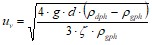
G – acceleration of gravity, m/sec2 ; d – diameter of particle, m; ![]() – the density of the disperse liquid or solid particles, kg/m3;
– the density of the disperse liquid or solid particles, kg/m3; ![]() – the density of the dispersion phase, kg/m3;
– the density of the dispersion phase, kg/m3;
![]() – the drag coefficient of the dispersion phase.
– the drag coefficient of the dispersion phase.
When the specified conditions are extremely difficult and sometimes impossible to affect the density of the continuous and dispersed phase, particle size and the drag coefficient of the dispersion phase, so the deposition rate can be increased by introducing additional driving forces separation of dispersed particles from the continuous phase. The most promising is a method of centrifugal separation of heterogeneous systems, in which the process takes place under the influence of centrifugal forces.
Swirling motion of the flow required for forming a field of centrifugal forces is formed by one of three methods [4-6]:
- tangential inlet; using mechanical swirl device; intensive rotational body elements channels (rotating pipe).
Application of a tangential inlet as the method for forming a swirling flow is limited by the complexity of the design and the large size of the device.
Creating a swirling flow by rotating the hull elements intensively channels need complicated supplying additional energy for the process, while a low value of the dynamic viscosity of the gas substantially reduces the performance of the method. Therefore, from the designs submitted by the simplest and most effective way to create a swirling movement is the use of mechanical devices, swirl, as this method allows you to:
- give a predetermined flow rate of twist; small overall dimensions, due to the axial location relative to the housing device; change the intensity of the swirl twist by replacing the device.
Thus, the most promising one is the centrifugal method of section of heterogeneous systems, to create swirling motion is still used mechanical swirlers that calls for theoretical and experimental studies of such devices, identifying their characteristic dependencies [7-11].
Results and discussion
1. Development of the construction of the vortex devices for gas purification
In order to increase the efficiency of gas purification from impurities in inhomogeneous Ufa State Oil Technical University of design vortex devices for gas purification, separation of non-homogeneous gas mixture which is under the influence of centrifugal forces.
| 1 – the case; 2 – connection for output the purified gas; 3 – twisting device; 4 – injection pipe; 5 – flanged; 6 – vortex separation chamber device; 7 – O connection for contaminants; 8 – inlet for contaminated gas entering |
Fig. 1. General view of the vortex devices for gas purification |
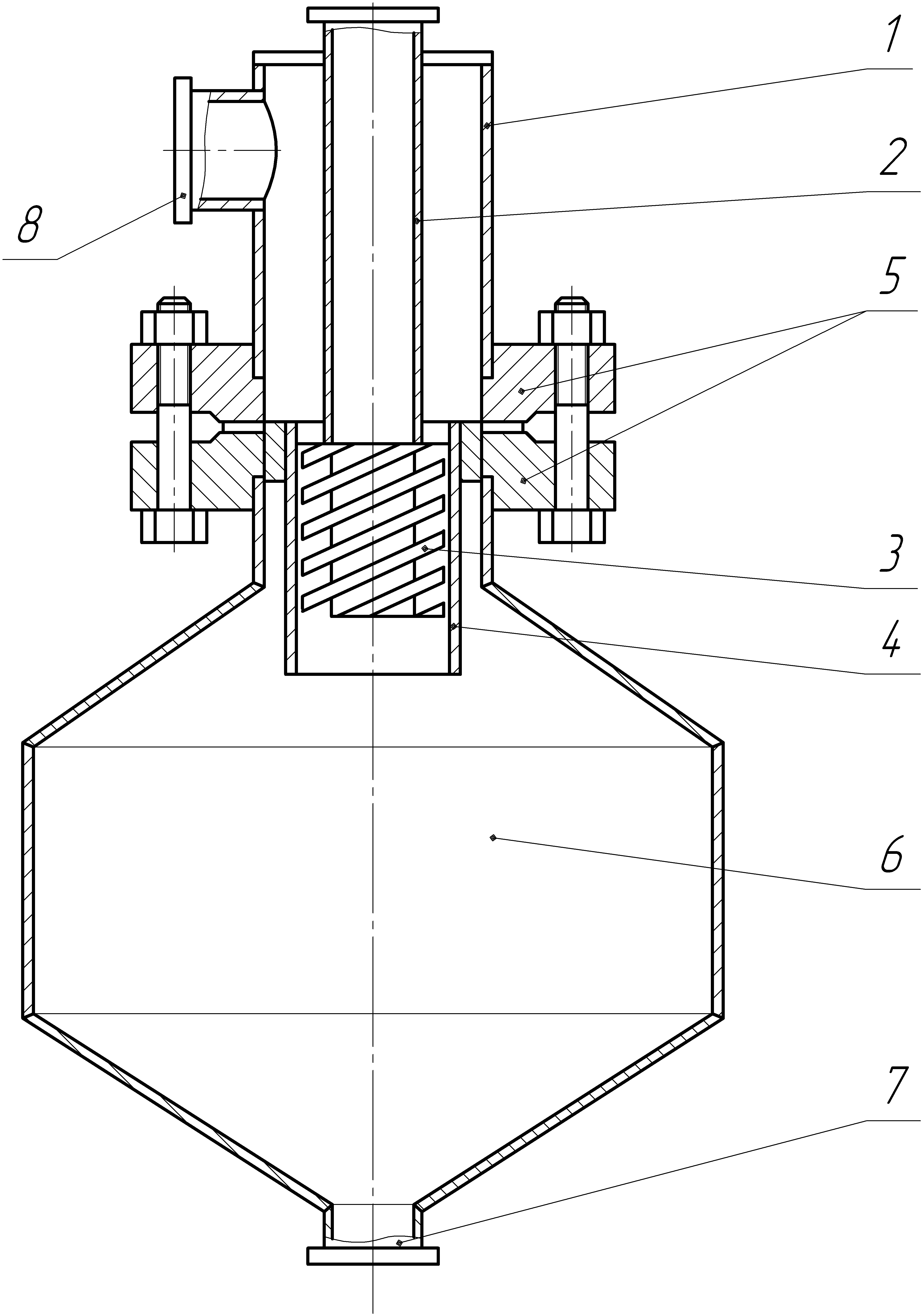
Vortex apparatus for purification of gases comprises a vertical cylindrical body. Inside the housing is located coaxial output connection for the purified gas, on an end portion of which is mounted a hollow swirling device, limited laterally injection the bottom of the housing unit by the connection flange attached vortex separation chamber with a nozzle for outputting impurities. Pipe for contaminated gas input situated on the side of the cabinet (fig. 1). The present swirling gas purification device operates as follows.
Cleaned gas flows through the pipe to enter the contaminated gas 8, the flow for further annulus defined between the inner surface of the housing and the outer wall of the outlet nozzle enters the swirling device 3. The device 3 purified gas stream with a spiral motion along the channels, in addition to axial, rotational acquires motion. Translational-rotational motion of the flow leads to a centrifugal force under the action of which the majority of heterogeneous impurities present in the gas is separated and accumulates on the inner surface of the injection tube 4, where larger and under the influence of gravitational and inertial forces descend. Further nonuniform gas flow enters the vortex separation chamber unit 6 attached to the bottom of the housing via a flanged connection 5. The vortex chamber is a second separation step the gas stream of 2: purified gas and heterogeneous impurities which are output therefrom, respectively, through pipes 2 and 7, which are located at the top and bottom of the separation chamber 6 apparatus.
2. The method of calculating the efficiency of the vortex devices for gas purification
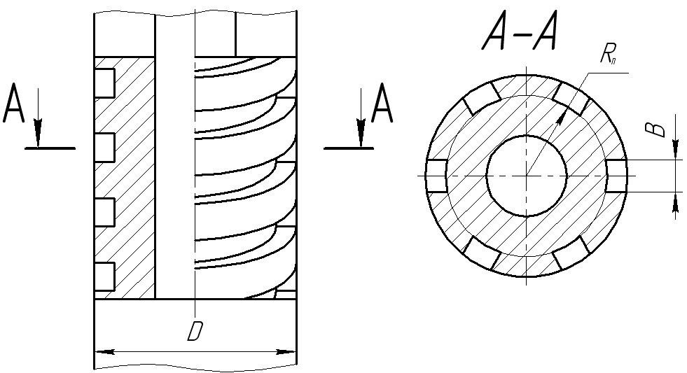
Consider the forces acting on the flow as it moves in the spiral channels swirl device (fig. 2).
|
Fig. 2. General view of the swirling vortex element devices for gas purification |
The axial velocity in the grooves of the swirling device according to the flow of purified gas:
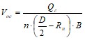 , (2)
, (2)
Qг – consumption of gas, m3/sec; n – the number of channels in the spiral swirling device;
D – the outer diameter of the swirl device, m; Rп – the outer radius of the base of the grooves, м; B – the width of the grooves, m.
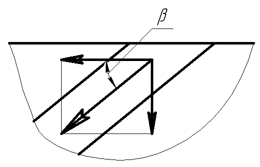
Designating a step spin spiral through h, we define the angle of deflection of the total velocity vector in the grooves of the swirling device from the vertical direction:
![]() (3)
(3)
The tangential velocity of the flow as it moves in the grooves of the swirling device (fig. 3):
![]() . (4)
. (4)
Substituting equation (2), (3), (4) we obtain:
![]() , (5)
, (5)
Qg – consumption of gas, m3/sec; D – the outer diameter of the swirl device, m; Rп – the outer radius of the base of the grooves, m; n – the number of channels in the spiral swirling device; h –twisting spiral channels, m; B – the width of the grooves, m.
|
Fig. 3. The flow velocity vector as it moves in the grooves twisting device |
The centrifugal acceleration, which occurs under the action of separation of the homogeneous gas mixture based on the equation (5):
![]() . (7)
. (7)
The rate of deposition of particles:
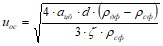 , (8)
, (8)
аca – centrifugal acceleration acting on the flow, m/sec2; d – diameter of particle, m;
![]() – the density of the disperse liquid or solid particles, kg/m3;
– the density of the disperse liquid or solid particles, kg/m3; ![]() – the density of the dispersion phase, kg/m3;
– the density of the dispersion phase, kg/m3; ![]() – the drag coefficient of the dispersion phase.
– the drag coefficient of the dispersion phase.
To remove heterogeneous impurities from the gas stream is necessary that the particles by centrifugal force reached the inner surface of the cylinder during the motion in swirling spiral channel device, that is necessary to satisfy the inequality:
![]() (9)
(9)
t – deposition time, sec.
The deposition time is equal to the time of the flow in the spiral-channel closed-limiting device:
![]() . (10)
. (10)
In view of (10) the condition (9) takes the form:
![]() , (11)
, (11)
где uос – the rate of deposition of particles, m/sec;
L – the length of the swirl device, m;
D – the outer diameter of the swirl device, m;
Rп – the outer radius of the base of the grooves, m;
n – the number of channels in the spiral swirling device;
h –twisting spiral channels, m;
B – the width of the grooves, m;
Qg – consumption of gas, m3/sec.
Consider the worst case, the right-hand side of (11) is equal to the left and from the resulting system of equations (7), (8) and (11) define a minimum diameter of captured particles of the dispersed phase:
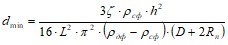 (12)
(12)
![]() – the drag coefficient of the dispersion phase;
– the drag coefficient of the dispersion phase; ![]() – the density of the disperse liquid or solid particles, kg/m3;
– the density of the disperse liquid or solid particles, kg/m3; ![]() – the density of the dispersion phase, kg/m3; h –twisting spiral channels, m; L – the length of the swirl device, m; D – the outer diameter of the swirl device, m; Rп – the outer radius of the base of the grooves, m.
– the density of the dispersion phase, kg/m3; h –twisting spiral channels, m; L – the length of the swirl device, m; D – the outer diameter of the swirl device, m; Rп – the outer radius of the base of the grooves, m.
From the resulting theoretically based, it follows that the quality of the gas purification process does not depend on the number and width of the spiral channels, and determines the size is the diameter of the inner and outer surfaces of the groove and the pitch of the helix. At the same time we should not forget that a large number of spiral channels and even complicates the design, but allows us to give a uniform flow of spin on a short section of the swirling device. The absence among the determinants of initial flow rate can be explained by the fact that an increase in the rate of growth at the same time centrifugal separation factor is a reduction of the time division inhomogeneous medium, which is fully offset by an increase of the driving force. It should be noted that the above calculation was made without taking into account several factors, among which are the following:
- in the above calculations have ignored the change in density of the gas, occurring when the pressure; number of heterogeneous impurities is small compared with the amount of gas; precipitated particles heterogeneous contaminants under the action of gravity forces are completely removed from the swirling vortex device.
However, these formulas can be used for a preliminary calculation process vortex developed for gas cleaning devices.
Conclusions
A device is designed to clean the stream, a process which takes place with intensive centrifugal force that allows for more efficient separation of inhomogeneous media in comparison with other types of deposition. The analytical performance of the device depending on the geometry of the twisting device. They imply that improving the efficiency of gas purification is achieved mainly by reducing the depth of the spiral channels of the swirl device, as well as an increase in intensity with decreasing spin step.References
V. G. Afanasenko, E. V. Boev, S. P. Ivanov, E. A. Nikolaev. The separation process in industrial cooling towers. Butlerov Communications. 2011. Vol.27. No.13. P.81-84. ROI: jbc-02/11-27-13-81 V. G. Afanasenko, E. V. Boev, E. A. Nikolaev. The peculiarity of separation and structural design drop fenders cooling towers. Water: chemistry and ecology. 2013. No.7(61). P.99-108. (russian) V. G. Afanasenko. Features of the separation process in evaporative cooling systems recycle water. In: OIL & GAS WEST SIBERIA Proceedings of scientific conference. Tyumen. 2009. P.335-336. (russian) A. G. Kasatkin. Basic processes and apparatuses of chemical technology. Ed. 9th. Moskow: Chemistry. 1973. 752p. (russian) V. M. Ramm Absorption of gases. Ed. 2th. Moskow: Chemistry. 1976. 656p. V. G. Afanasenko, E. V. Boev, E. A. Nikolaev. Classification separation packing cooling towers. Chemical engineering. 2010. No.7. P.10-11. V. G. Afanasenko, E. V. Boev, S. P. Ivanov, E. A. Nikolaev. Using the forces of centrifugal separation in the process of collecting the fine droplet cooling towers. Chemical industry today. 2008. No.2. P.38-41. (russian) F. Sh. Khafizov, V. G. Afanasenko, E. V. Boev. Use of vortex apparatuses in gas cleaning process. Chemical and Petroleum Engineering. 2008. Vol.44. No.7-8. P.425-428. F. Sh. Khafizov, V. G. Aphanasenko, Sh Khaybrahmanova, I. F. Khafizov use of cavitation vortex effects in the process of absorption purification of process gases from hydrogen sulphide. Refining and Petrochemicals. Scientific and technical achievements and best practices. 2007. No.11. P.49-53. (russian) V. G. Afanasenko. Evaluation of energy consumption for carrying out hydro-static processes in direct-flow devices. Collection of scientific works Sworld. 2010. Vol.7. No.4. P.93-94. (russian)In the Russian version of this article, the Reference Object Identifier – ROI: jbc-01/15-43-7-135
Разработка конструкции и методики расчета
вихревого устройства для очистки газов
© *+ и
Кафедра «Оборудование нефтехимических заводов». Филиал ФГБОУ ВПО «Уфимский государственный нефтяной технический университет» в г. Стерлитамаке.
пр. Октября, 2. г. Стерлитамак, 453100. Республика Башкортостан. Россия.
Тел.: +7 (3473) 24-25-12. E-mail: *****@***ru
_______________________________________________
*Ведущий направление; +Поддерживающий переписку
Ключевые слова: сепарация, очистка газов, вихревое движение, центробежная сила.
Аннотация
Очистка технологических газов – это один из самых распространенных процессов предприятий газовой и нефтехимической промышленности. Он проводится на различных стадиях производства, как для подготовки газообразного сырья основного органического синтеза, так и для очистки его продуктов. Очистке также подвергаются газы перед выбросом их в атмосферу с целью уменьшения содержания вредных примесей, негативно влияющих на экологию. В данной статье рассмотрены особенности процесса разделения неоднородных газовых смесей в условиях закрученного движения, а также представлена конструкция устройства для проведения данного процесса.
