
Партнерка на США и Канаду по недвижимости, выплаты в крипто
- 30% recurring commission
- Выплаты в USDT
- Вывод каждую неделю
- Комиссия до 5 лет за каждого referral
Investigation of the Input Unit of Frequency Converter
I. Rankis, A. Zhiravecka, I. Bunina
Riga Technical University (Riga, Latvia)
*****@***rtu. lv, *****@***rtu. lv
Abstract – The paper considers scheme of single-phase input unit with AC circuit reactor of frequency converter, its operation, dependencies of characteristics on parameters of the scheme and influence on supply network.
INTRODUCTION
The modern input units of the frequency converter are formed according to either „diode rectifier - capacitor” or „diode rectifier – filter reactor - capacitor” principle [1, 2]. In the first case from the AC network the short pulses of high amplitude are consumed that determines a very poor form of the supply current with high factor of harmonics distortion THD [3]. However the capacitor voltage is close to the amplitude of the sine-form supply voltage that provides the necessary value of RMS voltage at the output of inverter.
The second variant improves the form of current and its THD is approximately 0,3-0,4, i. e., acceptable enough. Though as the average value of the voltage across the filter reactor is zero, the voltage of the capacitor is equal to that of diode rectifier output, that in the case of single phase bridge contains only 0,9 of the supply RMS voltage U1. For example, if U1=220V, then the capacitor voltage is 198 V that is not enough to get necessary voltage, 3x220V, at the output of inverter in the realization without transformer.
As an alternative variant the input unit with reactor L in AC circuit before the bridge and capacitor in its output could be considered (Fig.1). In this realization the form of network current is satisfactory as well as capacitor voltage can achieve high enough values. The goal of this paper is to investigate key parameters and features of this scheme.
II. PROCESSES IN THE SCHEME
To simplify the description of the processes it could be accepted that capacitor C is of high enough capacity that in its turn provides an unchangeable voltage across its clamps in quasi-stationary process, i. e., uC=UC and load current then is fully smoothed (isl = Isl).
During each half-cycle of supply voltage a current through reactor L flows only from the moment ts when
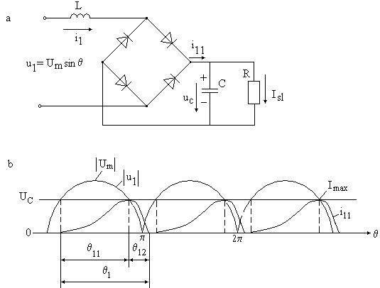
Fig.1. Scheme of the investigated single-phase AC input unit (a) and diagram of rectifier output current (b).
![]() , (1)
, (1)
that leads to the current initial moment
![]() . (2)
. (2)
The reactor current reaches its maximum value at the time moment
![]() , (3)
, (3)
when from the following ![]() . Therefore the increasing of the current i11 from 0 to Im lasts
. Therefore the increasing of the current i11 from 0 to Im lasts
![]() . (4)
. (4)
Current i11 during its increment time can be defined from the differential equation
![]() , (5)
, (5)
where t≥ts. The solution of this equation is
![]() , (6)
, (6)
where i11≥0. At the end of the increment time
![]() . (7)
. (7)
Then, as u1<UC, current i11 starts its decreasing to zero during time interval t12 . It results in intermittent mode of the current i11 , so long as UC>0,6Um.
However it is important to define the real value of UC depending on load resistance R. The capacitor voltage increases in its value when i11>Isl and decreases when i11<Isl. As the capacitor average current in steady-state is zero the average i11 is equal to Isl. But the direct integration of expression (6) is complicated as the time interval t1 of the current flow is difficult to be defined and calculated. Thus for the approximate calculations current i11 could be accepted as of triangle form with height Imax and base t1 and then
![]() , (8)
, (8)
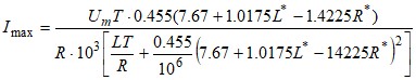
where amplitude Imax can be approximately calculated from
![]() . (9)
. (9)
In order to apply these simplified expressions it is necessary to define the coherence of interval t1 with parameters L and R with the help of computer model. The obtained dependences of t1=f(R) at different L (Fig.2) within the considered parameter range 1≤R≤10Щ, 1≤L≤5mH, Um=312V, f=50Hz, C=20000мF can be considered as close to linear.
This implies the calculation of interval t1 with a low error as
![]() . (10)
. (10)
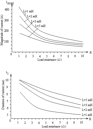
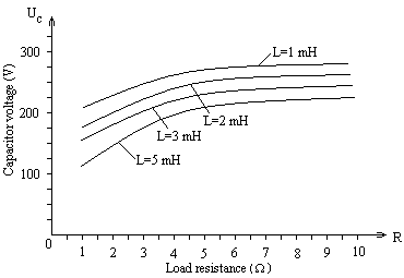
Fig.2. Characteristics from computer modeling of the scheme: magnitude of current Imax=f(R) , duration of current pulse t1=f(R) and voltage of capacitor UC=f(R) at different values of rector’s inductance L within the determined parameter range
Important is restriction that t1≤10 ms. Here the normalized parameters L* and R* are within the range from -1 (the lowest value) to +1 (the highest value) and determined as
![]() . (11)
. (11)
From the computer model we can also conclude that time
demonstrates that with the decreasing of values of the load resistance and inductivity of the reactor the amplitude of the current increases, but the average value of the capacitor voltage decreases with the decreasing of the load resistance and inductivity increasing.
Applying the above given statistical expression the voltage of the capacitor is defined as
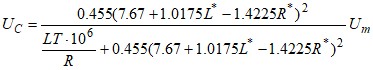 .(12)
.(12)
And with the same operation,
 .(13)
.(13)
The obtained equations allow calculation t1, UC and Im with a comparatively low error (Table 1).
TABLE 1
ESTIMATION OF THE ERROR OF CALCULATIONS
Parameters | L* | R* | Computer model | Calculation |
t1 | -1 | -1 | 8,2 ms | 8,075 ms |
-1 | +1 | 5,12 ms | 5,23 ms | |
+1 | +1 | 7,39 ms | 7,26 ms | |
+1 | -1 | 10 ms | 10 ms | |
UC | -1 | -1 | 203,7 V | 186,37 V |
-1 | +1 | 270,5 V | 268,9 V | |
+1 | +1 | 226,8 V | 220,2 V | |
+1 | -1 | 107 V | 99 V | |
Im | -1 | -1 | 426,8 A | 461,57 A |
-1 | +1 | 95,4 A | 102,8 A | |
+1 | +1 | 55,1 A | 60,66 A | |
+1 | -1 | 173,6 A | 195,7 A |
III. POWER INDICES OF THE SCHEME
Assuming the form of the network current during the half-period as triangle pulse the RMS current is calculated as
![]() , (14)
, (14)
and the total power consumed from the network is
![]() . (15)
. (15)
The active power is
![]() . (16)
. (16)
Calculating power factor as a ratio of these two values taking into account the obtained before expressions (8), (12), (13)
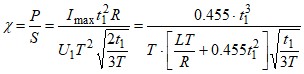 . (17)
With the help of this equation P/S ratio dependence on R and L changes can be calculated (Table 2).
TABLE 2
ESTIMATION OF THE POWER FACTOR INDEX
Parameter | L* | R* | Computer model | Calculation |
I1ef, A | -1 | -1 | 257 | 239,46 |
-1 | +1 | 44,07 | 42,92 | |
+1 | +1 | 31,07 | 29,84 | |
+1 | -1 | 120,3 | 113 | |
S, VA | -1 | -1 | 56540 | 52683 |
-1 | +1 | 9695 | 9443 | |
+1 | +1 | 6835 | 6565 | |
+1 | -1 | 26466 | 24857 | |
P/S | -1 | -1 | 0,728 | 0,66 |
-1 | +1 | 0,752 | 0,765 | |
+1 | +1 | 0,75 | 0,738 | |
+1 | -1 | 0,438 | 0,39 |
It is obvious that computer model as well as approximate calculations provide close enough results allowing to conclude that with low load resistance power indices increase with the decreasing of input reactor inductivity. Fig.3. represents dependences of ч=f(R) at different values of L obtained in the computer simulation and calculations as well for comparison. From the graph it is seen that the unit provides the highest power parameters within the middle of the load zone.
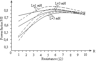
Fig.3. Dependences of ч=f(R) at different L obtained in the computer simulation (uninterrupted line) and in the calculations (dashed line)
The second power parameter is the index of total harmonic distortions of the network current. Thus for the calculations the RMS value of current I1(1) must be calculated. Assuming the form of the network current during the half-period as triangle the RMS value of the basic harmonic is approximately determined as
![]() (18)
(18)
and as a result THD is
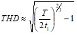 . (19)
Depending on R* and L* values in the investigation range the following estimation expression can be obtained with the use of computer modeling
![]() . (20)
. (20)
Figure 4 demonstrates graphs THD=f(R) obtained in the computer modeling and with the help of estimating expression at different L. The estimating expression gives the results close enough to those experimentally obtained.
IV. SELECTION OF THE PARAMETERS
Inductivity of reactor L can be defined according to a necessary ![]() ratio with the different given load resistances. Expression (12) could be applied for this aim taking into account that this satisfactory relation is provided within the zone -1≤L* ≤+1. Still with sufficiently good results that could be applied also with L* ≥-1.3. Thus, for example, if R*=-0.8 and the ratio of capacitor voltage is
ratio with the different given load resistances. Expression (12) could be applied for this aim taking into account that this satisfactory relation is provided within the zone -1≤L* ≤+1. Still with sufficiently good results that could be applied also with L* ≥-1.3. Thus, for example, if R*=-0.8 and the ratio of capacitor voltage is ![]() , in accordance with equation (12), if the voltage of capacitor is smoothed, a reactor with inductivity L*=-1.3 (0.4 mH within the assumed data range) can be used. From the computer model the same voltage ratio R*=-0,8 can be obtained with L*=-1.35 (i. e., L=0.3 mH).
, in accordance with equation (12), if the voltage of capacitor is smoothed, a reactor with inductivity L*=-1.3 (0.4 mH within the assumed data range) can be used. From the computer model the same voltage ratio R*=-0,8 can be obtained with L*=-1.35 (i. e., L=0.3 mH).
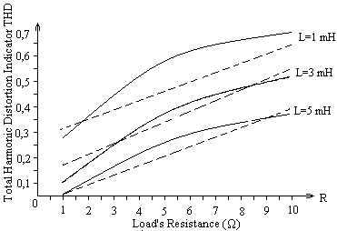
Fig.4. Characteristics THD=f(R) at different L in computer modelling (uninterrupted line) and in calculation (dashed line)
The selection of a necessary capacitance can be realized in accordance with the approximate expression
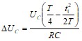 , (21)
where ДUC is a full increment of an instantaneous value of the capacitor C voltage during a half-period (fig.5.). The expression is approximate assuming the form of the output current of the rectifier as triangle (Fig.5) and applying the equation (8). For example, assuming ![]() with R*=-1 and L*=-1 the necessary capacity is 33700 мF.
with R*=-1 and L*=-1 the necessary capacity is 33700 мF.
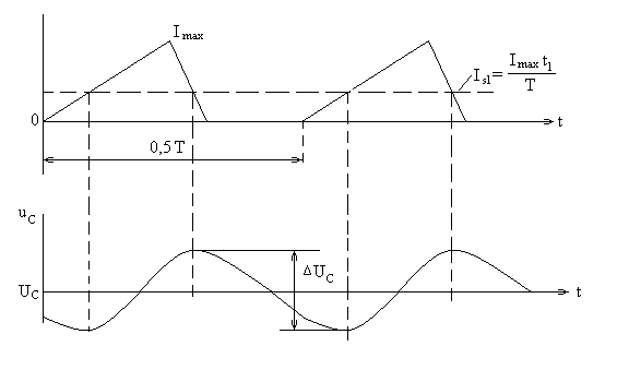
Fig.5. Diagram of voltage ripple of the capacitor C voltage during a half-period
V. CONCLUSIONS
1.The considered topology of the input unit provides enough high voltage of the output capacitor of the rectifier as well as satisfactory form of the current of single-phase AC network.
2. The precise calculations according to differential equations in this scheme are complicated therefore a simplified approach could be applied on the base of linearization of the network current form and statistical estimation of the dependences of the duration of the current impulse within half-period on the inductivity of the reactor and load resistance, that can be considered close to linear relations.
3. To obtain a higher output voltage at lower load resistances the decreasing of the amplitude of reactor current is required, that decreases the duration of the current impulse and worsens the power factor and harmonic distortion.
4. In the considered range of L and R parameters with the network voltage 220V, 50 Hz the mathematical expectation of the voltage is 221.75V, the duration of the impulse of network current is 7.65ms, the amplitude of current impulse is 102.8A, power parameters - P=8941W, S=11435VA, P/S=0.78 and THD of the network current is 0.346.
REFERENCES
[1] Power Electronics. Handbook/ Muhammad H. Rashid, Editor in chief. Academic Press: NY,2001, 895 pp.
[2]. N. Mohan, T. Undeland, W. Robbins Power Electronics: Converters, Applications and Design, NY, 1989, 667 pp.
[3]. D. A.Jarc, R. G. Schieman, Power Line consideration for Variable Frequency Drives, IEEE Trans. on Ind. Applic. Vol. IAS, No5 1985,pp.1099-1105.
