

Партнерка на США и Канаду по недвижимости, выплаты в крипто
- 30% recurring commission
- Выплаты в USDT
- Вывод каждую неделю
- Комиссия до 5 лет за каждого referral
Всемирная конференция радиосвязи (ВКР-15) | |
МЕЖДУНАРОДНЫЙ СОЮЗ ЭЛЕКТРОСВЯЗИ | |
| |
ПЛЕНАРНОЕ ЗАСЕДАНИЕ | Документ 72-R |
16 октября 2015 года | |
Оригинал: английский | |
Германия, Франция | |
Воздействие предела п. п.м −113 дБВт/(мІ ⋅ МГц) на работу РСС в полосе частот 1452−1492 MГц | |
| |
Пункт 1.1 повестки дня |

1.1 рассмотреть дополнительные распределения спектра подвижной службе на первичной основе и определение дополнительных полос частот для Международной подвижной электросвязи (IMT), а также соответствующие регламентарные положения в целях содействия развитию применений наземной подвижной широкополосной связи в соответствии с Резолюцией 233 (ВКР-12);
Обзор технического исследования
В варианте C1 текста ПСК для полосы частот 1452−1492 МГц предлагается следующее:
"в целях упрощения сосуществования IMT и РСС в полосе частот 1452−1492 МГц в текущие регламентарные процедуры, регулирующие взаимоотношения РСС и наземных служб, будут внесены изменения путем включения значения п. п.м. [−113 дБВт/м2/МГц] в Статью 21 РР, с тем чтобы обеспечить более стабильную (долговременную стабильность) ситуацию в отношении IMT. Будут внесены изменения в Приложение 5 к РР, с тем чтобы обеспечить странам, желающим применять процедуру координации по п. 9.11 РР, возможность применения этой процедуры. Вследствие этого, к РСС будет применяться предельное значение п. п.м. в отношении всех наземных служб, за исключением стран, желающих и далее применять п. 9.11 РР, в силу более жестких требований к защите (например, в целях защиты систем телеметрии)".
Обоснование значения п. п.м. −113 дБВт/(м2 ⋅ МГц) приводится в отчете ОЦГ 4-5-6-7. Это значение п. п.м. обеспечивает надлежащую защиту пользовательского оборудования IMT и имеет значительно менее строгий характер, чем значения п. п.м., применимые к соседним или близлежащим полосам.
В настоящем документе содержится более подробный анализ этого вопроса, который свидетельствует о том, что это значение п. п.м оказывает ограниченное воздействие на системы РСС. Результаты анализа показывают, что, учитывая существующую информацию о координации и заявлении в отношении спутниковых сетей РСС в полосе частот 1452−1492 МГц, установление предлагаемого предельного значения п. п.м. −113 дБВт/(м2 ⋅ МГц) приведет к весьма ограниченным конструктивным ограничениям для систем РСС. Эти предельные значения п. п.м обеспечат надлежащую защиту оконечных станций IMT в пределах полосы частот 1452−1492 МГц, позволяя при этом осуществлять покрытие стран, желающих войти в состав систем РСС и поэтому соглашающихся с тем, что это предельное значение п. п.м. будет превышено над их территориями.
Annex
(English only)
Impact of a −113 dBW/(m2 · MHz) pfd limit on BSS operations
in the band 1 452-1 492 MHz
1 Introduction
Option C1 of the CPM text on WRC-15 agenda item 1.1 for the band 1 452-1 492 MHz proposes to set a pfd value of −113 dBW/(m2 · MHz) in Article 21 of the Radio Regulations. This pfd value provides an appropriate protection of IMT user equipment. The study contained in this Annex provides a further analysis showing the limited impact of this pfd value on BSS systems.
2 Analysis of the coverage area of different BSS systems
2.1 Characteristics of the BSS systems
The characteristics of the BSS satellite networks in the band 1 452-1 492 MHz that are studied in this document were taken from special sections published in BR IFIC. When a BSS satellite network uses multi spot beams and covers different areas, the study distinguishes among them the various cases in the following analysis. The following table lists all the cases that are addressed in this document.
Table 1
List of studied BSS satellite networks in the band 1 452-1 492 MHz
Satellite Name | Longi-tude | Notifying administration | Status1 | Beam Name | |||||
AFRIBSS | 21°E | USA | N | AD | CD | BD | AD2 | CD2 | BD2 |
ASIABSS | 105°E | Australia | N | AD | CD | BD | |||
CHINASAT-xx | 92.2°E 87.5°E 126°E 136°E 163°E 51.5°E 110.5°E 125°E 163°E 87.5°E 115.5°E | China | N C C C C C C C C C C | LDCN LD1R LBDR LBDR LDR LDR LBDG LBDG LBDG LBDG LBDR | LD2R LBDR LBDR LBDR LBDR | LD3R | |||
DFH-3-OC M | 87.5°E | China | N | EL1 | |||||
SADKO | 85.4°E | Russian Federation | N | LEBR | |||||
INDOSTAR-1 INDOSTAR-2 INDOSTAR-3 INDOSTAR-4 | 107.7°E 119.1°E 107.5°E 118.9°E | Indonesia | N N N N | LBN |
The purpose of the study is to evaluate if the proposed pfd limit included in the CPM Report on WRC-15 agenda item 1.1 (i. e. −113 dBW/(m2 · MHz)) has an impact on the coverage requirements of the intended service areas of BSS systems operating within the band 1 452-1 492 MHz.
Technical characteristics of BSS satellite networks were extracted from the SRS database through the SNS Query Builder software2 and are shown in Table 2 below.
Table 2
Characteristics of BSS satellite networks in the band 1 452-1 492 MHz
Satellite and/or Beam Name | Pe max | Pe min | GTx | EIRPmax | EIRPmin | B (MHz) |
AD AFRIBSS | 23.8 dBW | 10.7 dBW | 29 dB | 52.8 dBW | 39.7 dBW | 3 |
BD AFRIBSS | 23.8 dBW | 10 dBW | 29.7 dB | 53.5 dBW | 39.7 dBW | 3 |
CD AFRIBSS | 23.8 dBW | 10.7 dBW | 29 dB | 52.8 dBW | 39.7 dBW | 3 |
AD2 AFRIBSS | 23.8 dBW | 2.5 dBW | 30 dB | 53.8 dBW | 32.5 dBW | 2.6 |
BD2 AFRIBSS | 23.8 dBW | 9.2 dBW | 30.5 dB | 54.3 dBW | 39.7 dBW | 2.6 |
CD2 AFRIBSS | 23.8 dBW | 2.5 dBW | 30 dB | 53.8 dBW | 32.5 dBW | 2.6 |
AD ASIABSS | 23.8 dBW | 19.8 dBW | 30 dB | 53.8 dBW | 49.8 dBW | 2.6 |
BD ASIABSS | 23.8 dBW | 19.8 dBW | 30.5 dB | 54.3 dBW | 50.3 dBW | 2.6 |
CD ASIABSS | 23.8 dBW | 19.8 dBW | 30 dB | 53.8 dBW | 49.8 dBW | 2.6 |
LDCN CHINASAT-92.2E | 25 dBW | 21 dBW | 29 dB | 54 dBW | 50 dBW | 2.6 |
CHINASAT-A5 (87.5) LD1R/LD2R/LD3R | 31.8 dBW | 2.6-17 dBW | 37 dB | 68.8 dBW | 39.6 dBW | 2.6 |
CHINASAT-C20 (126) | 31.8 dBW | 2.6-20 dBW | 37 dB | 68.8 dBW | 39.6 dBW | 2.6 |
CHINASAT-C21 (136) | 31.8 dBW | 2.6-20 dBW | 37 dB | 68.8 dBW | 39.6 dBW | 2.6 |
CHINASAT-CL11 (163) | 31.8 dBW | 2.6-20 dBW | 37 dB | 68.8 dBW | 39.6 dBW | 2.6 |
CHINASAT-CL2 (51.5) | 31.8 dBW | 2.6-20 dBW | 37 dB | 68.8 dBW | 39.6 dBW | 2.6 |
CHINASAT-D-110 (110.5) | 31.8 dBW | 2.6-20 dBW | 37 dB | 68.8 dBW | 39.6 dBW | 2.6 |
CHINASAT-125E | 31.8 dBW | 2.6-20 dBW | 37 dB | 68.8 dBW | 39.6 dBW | 2.6 |
CHINASAT-163E | 31.8 dBW | 2.6-20 dBW | 37 dB | 68.8 dBW | 39.6 dBW | 2.6 |
CHINASAT-87.5E | 31.8 dBW | 2.6-20 dBW | 37 dB | 68.8 dBW | 39.6 dBW | 2.6 |
CHINASAT-DL4 (110.5) | 31.8 dBW | 2.6-20 dBW | 37 dB | 68.8 dBW | 39.6 dBW | 2.6 |
CHINASAT-DL5 (115.5) | 31.8 dBW | 2.6-20 dBW | 37 dB | 68.8 dBW | 39.6 dBW | 2.6 |
CHINASAT-DL6 (125) | 27.7 dBW | 17.7 dBW | 37 dB | 64.7 dBW | 54.7 dBW | 5 |
EL1 DFH-3-OC | 19.9 dBW | 11.9 dBW | 39 dB | 58.9 dBW | 50.9 dBW | 2.6 |
LEBR SADKO-1 | 16 dBW | 13 dBW | 43 dB | 59 dBW | 56 dBW | 1.35 |
LBN INDOSTAR-1,2,3,4 | 15 dBW | 15 dBW | 28.9 dB | 43.9 dBW | 43.9 dBW | 0.3 |
2.2 Methodology for performing the coverage area of the BSS
Based on the technical characteristics of BSS satellite networks that were published in the BR IFIC and using the ITU-R Software GIMS3, pfd values over geographic areas of the Earth have been derived for each satellite network and beam.
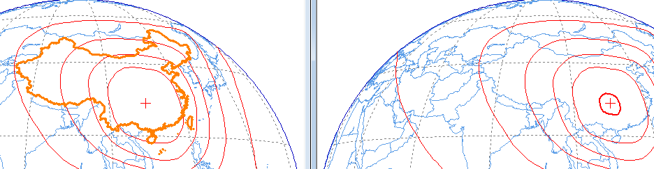
As an example, the following figure depicts the service area (left-hand side, bold orange curve) and the coverage area (left side, red curve) of the CHINASAT-92.2E satellite network. GIMS also enables to display the zone corresponding to a constant pfd value (right-hand side, small red bold circle corresponding to a pfd value of −113 dBW/(m2 · MHz)).
Figure 1
Examples of service area, coverage area constant pfd area of a BSS satellite network
2.3 Results
Based on the previous assumptions, results of the analysis are provided in Table 3 below for the satellite networks that were listed in Table 1.
Recalling the pfd formula:  where d is the distance between the BSS satellite and the point of the Earth where the pfd is computed. maximum pfd value within the service area and at its border is computed for each satellite and/or beam (although there may be some different (EIRPmax, B) combinations for the same beam in the BR IFIC special sections, only one value is retained for each beam in the following table and corresponds to the worst case of the highest power spectral density value). Note that the results may change with different beams of the same satellite network.
Table 3
pfd values within and outside service areas of BSS satellite networks in the band 1 452-1 492 MHz
Satellite and/or Beam Name | EIRPmax | Bandwidth (MHz) | Max. pfd within the service area (dBW/(m2 · MHz)) | Max. Pfd at the border of the service area (dBW/(m2 · MHz)) |
AD AFRIBSS | 52.8 dBW | 3 | < −113 | < −113 |
BD AFRIBSS | 53.5 dBW | 3 | < −113 | < −113 |
CD AFRIBSS | 52.8 dBW | 3 | < −113 | < −113 |
AD2 AFRIBSS | 53.8 dBW | 2.6 | > −113 | < −113 |
BD2 AFRIBSS | 54.3 dBW | 2.6 | > −113 | < −113 |
CD2 AFRIBSS | 53.8 dBW | 2.6 | > −113 | < −113 |
AD ASIABSS | 53.8 dBW | 2.6 | > −113 | < −113 |
BD ASIABSS | 54.3 dBW | 2.6 | > −113 | < −113 |
CD ASIABSS | 53.8 dBW | 2.6 | > −113 | < −113 |
LDCN CHINASAT-92.2E | 54 dBW | 2.6 | > −113 | < −113 |
CHINASAT (Coordination | 68.8 dBW | 2.6 | > −113 | > −113 |
EL1 DFH-3-OC | 58.9 dBW | 2.6 | < −113 | < −113 |
LEBR SADKO-1 | 59 dBW | 1.35 | > −113 | > −113 |
LBN INDOSTAR | 43.9 dBW | 0.3 | < −113 | < −113 |
It can be noted that:
– Some BSS satellite networks have beams (e. g. AFRIBSS beams AD, BD, CD) that comply with the proposed pfd limit (−113 dBW/(m2 · MHz)) within the service area (see 4th column of the previous table), showing that in some cases the proposed pfd limit is higher than the pfd levels required to provide the intended service,
– other BSS satellite networks are able to comply with the proposed pfd limit at the border of their service area (e. g. ASIABSS beams),
– other BSS satellite networks do not meet the proposed pfd limit at the border of their service area (highlighted in red in the last column). These cases where the proposed pfd limit is exceeded outside the service area are listed in Table 4 below.
Table 4
List of BSS satellite networks in the band 1 452-1 492 MHz
for which the proposed pfd limit is exceeded outside the service area
Satellite and/or Beam Name | EIRPmax | Bandwidth (MHz) | Max. pfd within the service area (dBW/(m2 · MHz)) | Max. pfd at the border of the service area (dBW/(m2 · MHz)) |
CHINASAT (Coordination | 68.8 dBW | 2.6 | > −113 | > −113 |
LEBR SADKO-1 | 59 dBW | 1.35 | > −113 | > −113 |
More precisely, the results show:
For LEBR SADKO-1
Figure 2 depicts on the left-hand side the service area of the LEBR beam of the SADKO-1 satellite network (bold orange curve) and on the right-hand side the area where the proposed pfd limit of −113 dBW/(mІ · MHz) is exceeded (bold red curve). The coverage area of the SADKO-1 LEBR beam encompasses countries that are outside the service area (see geographic areas southern of the service area on the left-hand side of Figure 2).
Figure 2
Coverage area and constant pfd area of the LEBR beam of the SADKO-1 satellite network
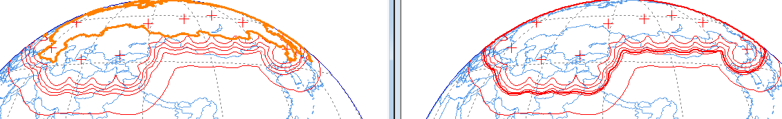
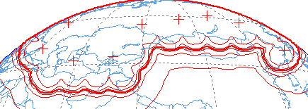
The proposed pfd limit is exceeded in some areas outside the territory of the Russian Federation, which constitutes the service area of the SADKO-1 LEBR beam. The result still remains the same if the satellite radiates with its lowest EIRP value (56 dBW), which is only 3 dB below the maximum EIRP, thus showing large areas outside of the service area where the produced pfd exceeds −113 dBW/(m2 · MHz) (see Figure 3 below).
Figure 3
Constant pfd area of the LEBR beam of the SADKO-1 satellite network
when emitting with its lowest EIRP level
There are two possibilities for the countries outside the service area but covered by the beam:
a) They wish to be part of the service area. Then they may accept that the pfd limit of −113 dBW/(m2 · MHz) does not apply over their territories.
b) They do not wish to be part of the service area. Then the beam on the satellite should be designed in a manner that avoids full coverage of these countries.
In both cases, the pfd limit of −113 dBW/(m2 · MHz) is exceeded only over territories within a limited distance (ranging from 30 km to 190 km for case a) and up to 70 km for case b)) from the border of the service area.
This could enable the notifying administration of the SADKO-1 satellite network:
– to adapt the technical characteristics of this BSS satellite network to ensure that it will not affect terrestrial services such as IMT by complying with the proposed pfd limit of −113 dBW/(m2 · MHz),
– in case where the impact is accepted by an administration neighbouring the service area, to reach agreement with it for such a pfd excess.
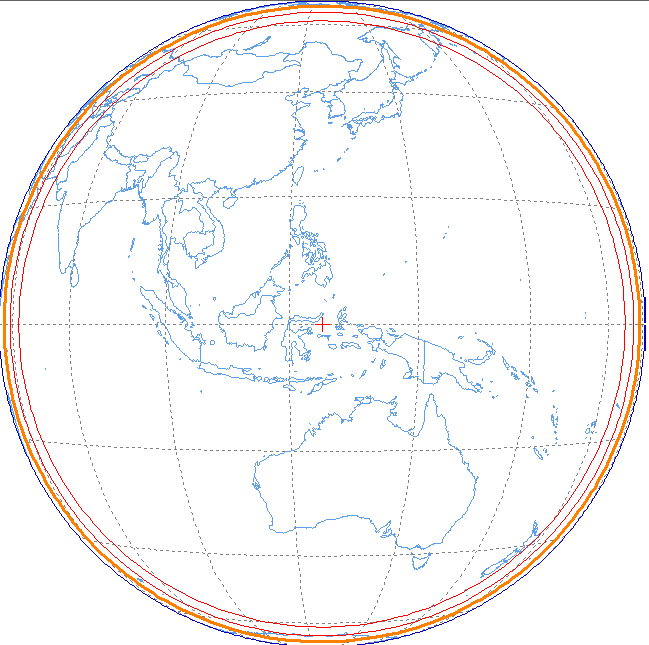
As an example of a possible technical adaptation, if the satellite EIRP is limited to 52 dBW (i. e. 4 dB below the submitted minimum EIRP), then the proposed pfd limit is nearly met outside the service area (see Figure 4). This EIRP level may reduce the BSS link margin within the service area and some other technical solutions (e. g. better beam shaping ) may be more appropriate.
Figure 4
Constant pfd area of the LEBR beam of the SADKO-1 satellite network
when emitting with a reduced EIRP level

For CHINASAT satellite networks
Among those files available in the space radiocommunication stations (SRS) reference database, there are coordination requests for which the associated BSS service area is large (see Figure 5 below).
Figure 5
Constant pfd area of the LEBR beam of the SADKO-1 satellite network
when emitting with a reduced EIRP level
This situation may be explained by emphasizing that the coverage is performed through:
– steerable spot beams,
– multiple spot beams to cover the large area (as depicted in orange circle in the above Figure) even they are not displayed in the publication.
Starting from pfd formula: 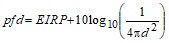 ,
,
When ![]()
![]() and TRx noise are available, Cmin (receiver sensitivity) can be derived:
and TRx noise are available, Cmin (receiver sensitivity) can be derived:
![]()
Recalling that: 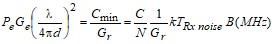
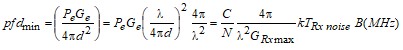
From the above formula, it is then concluded that the pfdmin value could be derived from the following parameters:
• Radio link budget: the C/N ratio (dB) is available in the IFIC special section
• receiver capabilities: the maximum antenna gain value GRx max and noise temperature TRx noise are available in the IFIC special section
Data related to coordination requests of CHINASAT satellite networks are given in the first five columns of Table 5 below and the pfdmin is then derived for each scenario. All orbital positions refer to the common four values of the GRx max, T, C/N parameters.
Table 5
Required minimum pfd value for various CHINASAT satellite networks
Orbital positions (°E) | Beam Names | C/N (dB) | Gr max (dB) | T (K) | pfdmin (dBW/(m2 · MHz)) |
51.5/ 163 | LDR | 13.2 13.4 13.5 13.2 | 5 11 17 2 | 280 200 150 280 | −111 −118.3 −125.4 −108 |
87.5 | LD1R, LD2R LD3R, LBDG LBDR | ||||
110.5 115.5 126 136 | LBDR | ||||
125 163 | LBDG, LBDR |
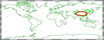
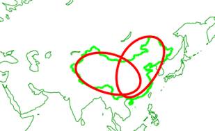
Several cases show required minimum pfd levels higher than the proposed pfd limit (i. e. −111 and −108 dBW/(m2 · MHz)). In order to assess if the proposed pfd limit (−113 dBW/(m2 · MHz)) quantitatively affects or not the coverage requirements of the BSS operator within its (large) service area, modelling the antenna pattern of the BSS transmitting satellite would be required to compute radio link budgets. Since BSS systems for this scenario are assumed to use steerable spot beams, Recommendation ITU-R S.672-4 was used to model the transmitting antenna pattern of these satellites. Based on that information, the proposed pfd limit (−113 dBW/(m2 · MHz)) is then derived and depicted by the red ellipse over the Chinese territory in the following figure. It can be seen that this ellipse is roughly included in the territory of the Chinese country (depicted in green).
Figure 6
Constant pfd area of a steerable spot beam pointed towards the Chinese territory
as modelled with Recommendation ITU-R S.672-4
One could object that such spot beam does not cover the whole territory (North East and North West of China) and that this red ellipse is close to 15 dB antenna gain discrimination isocurve from the antenna boresight, which is uncommon for antenna discrimination at the coverage edge (lower values are expected). Moreover, since ITU special sections do not provide any details on the actual coverage of spot beams, the following figure tries to demonstrate the feasibility of covering the Chinese territory by several spot beams (e. g. 2) for which each red ellipse depicts the area outside of which the proposed pfd limit (−113 dBW/(m2 · MHz)) is met.
Figure 7
Possible coverage of the Chinese territory with two spot beams
modelled with Recommendation ITU-R S.672-4
Since these spot beams overlap each other, a proper way to avoid/reduce BSS interference issues in the intersection zone would be to transmit on a different channel within each spot beam. As a matter of comparison, the elliptical curve for the highest pfdmin value (provided in Table 5 above, i. e. −108 dBW/(m2 · MHz)) is shown in blue below. The blue spot beam cannot cover entirely the most western part of the Chinese territory.
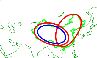
This approach leads to conclude that similarly to what was previously studied for other BSS systems (i. e. for satellites using fixed beams), the proposed pfd limit of −113 dBW/(m2 · MHz) does not cause additional constraint on the BSS operations for satellites equipped with steerable spot beams.
3 Conclusions
This study shows that, based on existing coordination and notification information regarding BSS satellite networks in the frequency band 1 452-1 492 MHz, a proposed pfd limit of −113 dBW/(m2 · MHz) will entail very limited design constraints for BSS systems. This pfd limit enables an appropriate protection of IMT terminal stations within the frequency band 1 452-1 492 MHz, while enabling coverage of countries willing to be part of a BSS systems and therefore accepting that this pfd limit will be exceeded over their territories.
______________
1 N: Notification, C: Coordination Request
2 https://www. itu. int/online/sns select Query Builder option in the left menu.
3 Graphical Interference Management System : http://www. itu. int/en/ITU-R/software/Pages/gims. aspx
