

Enthalpy
The enthalpy of a mass of a substance is a measure of its thermodynamic heat (or energy) content, whether the substance is liquid or vapour or a combination of the two. Within the Sl system it is measured in kiloJoules per kilogram. Enthalpy (H) is defined as: —
H = U +PV/M where H = enthalpy (kJ/kg)
U = internal energy (kJ/kg)
P = absolute pressure (kN/m2)
V = total volume of the system — liquid plus vapour (m3) and M = mass in the system (kg) [Note: Newtons = kg m/sec2; Joules = kg m2/sec2]
The total internal energy of a fluid is the thermodynamic energy attributable to its physical state. It includes sensible heat, latent heat, kinetic energy and potential energy. The PV term in the foregoing formula represents the energy available within a fluid due to pressure and volume.
Absolute values of enthalpy are not normally of practical interest —it is the changes of enthalpy which are important in the thermodynamic analysis of a process. Accordingly, the enthalpy of a system is usually expressed from an arbitrarily chosen zero. Since a change in enthalpy expresses the total energy change in a fluid as it passes through any thermodynamic process, it is a useful unit for the analysis of energy changes. This is particularly so in cyclic processes involving compression, expansion, evaporation or condensation such as are encountered in the reliquefaction of boil-off vapours. In such processes, changes in kinetic energy and potential energy are negligible and thus enthalpy changes are calculable from well-established thermodynamic data. Tabular presentation of enthalpy changes for some liquefied gases are available but for many applications the most widely used presentation is that found in Mollier diagrams. On one comprehensive chart the Mollier diagram plots many different factors against absolute pressure (log scale) and enthalpy (linear scale). Mollier diagrams are available for a wide range of fluids, including all the liquefied gases, and should be available on board every LPG ship for the cargoes transported.

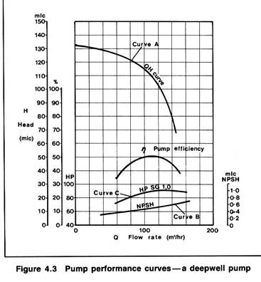
The flow-head curve (Curve A)
Curve A shows the pump capacity, given in terms of flow rate (normally m3/hr), as a function of the head developed by the pump, given in terms of metres liquid column (mlc). This curve is called the pump adopting metres liquid column and flow as the main criteria, the pump characteristic is the same, irrespective of the fluid being pumped. Taking curve A, shown in Figure 4. 3, the pump will deliver 100 m3/hr against a head difference of 115 mlc between ship and shore tanks. To convert this head into pressure the specific gravity of the cargo being pumped must be known.
For example, at a head of 105 mlc the increase in pressure across the pump when pumping ammonia at -330C with a specific gravity of 0. 68 would be:
105 x 0. 68 = 71. 4 mlc (water) = 71. 4/10. 2 = 7 barg.
(Note: — the factor 10. 2 in the foregoing equation denotes the height, in metres, of a water column maintained solely by atmospheric pressure)
The net positive suction head curve (Curve B)
Curve B shows the Net Positive Suction Head (NPSH) requirement for the pump as a function of flow-rate. The NPSH requirement at any flow rate is the positive head of fluid required at the pump suction over and above the cargo's vapour pressure to prevent cavitation at the impeller. For example, at a capacity of 100 m3/hr the NPSH requirement for the pump is 0. 5 mlc. This means that with a flow rate of 100 m3/hr a minimum head of cargo equivalent to 0. 5 metres is required at the pump suction to prevent cavitation. An over-pressure of 0. 03 bar in the cargo tank is equivalent to 0. 5 metres head when pumping ammonia at -330C.
NPSH considerations are particularly significant when pumping liquefied gases because the fluid being pumped is always at its boiling point. It must be remembered that if cavitation is allowed to occur within a pump, not only will damage occur to the impeller but the shaft bearings themselves will be starved of cargo. This will restrict cooling and lubrication at the bearing and damage will quickly result.
The power consumption curve (Curve C)
Curve C shows the power absorbed as a function of pump capacity. This curve is normally given for a specific liquid density and can be converted for any liquid by multiplying by the ratio of specific gravities. In this respect, of the cargoes normally transported in gas carriers, vinyl chloride has the highest specific gravity. This is about 0. 97 at its atmospheric boiling point. (Table 2. 5 gives details for other liquefied gases). In cases where cargo pump motors have been sized on the basis of LPG and ammonia cargoes, it will therefore be necessary to reduce discharge rates when pumping vinyl chloride in order to avoid overloading the motor.

LIQUEFIED GAS HANDLING (EXTRACT)
7.5.5 Cargo tank loading limits
Chapter 15 of the IGC Code recognizes the large thermal coefficient of expansion of liquefied gas and gives requirements for maximum allowable loading limits for cargo tanks. This is to avoid tanks becoming liquid-full under conditions of surrounding fire.
The maximum volume to which any tank may be filled is governed by the following formula:
LL = FL x (pR/pL), where:
LL = loading limit expressed in per cent which means the maximum liquid volume relative to the tank volume to which the tank may be loaded.
FL = filling limit = 98 per cent unless certain exceptions apply.
pR = relative density of cargo at the reference temperature.
pL = relative density of the cargo at the loading temperature and pressure.
The reference temperature (in the expression pR above) is defined as the temperature corresponding to the vapor pressure of the cargo at the set pressure of the relief valves. Some pressurized ships with Type 'C' tanks have a pressure capability of up to about 18 bars with relief valves being designed for this pressure. These loading limits impose a substantial cargo shut-out for fully pressurized ships loading cargo when operating in ambient conditions, well below 45°C which is the maximum operating temperature for which the pressure capabilities of such tanks are designed.
In the case of cargo tanks on fully refrigerated ships, the Gas Codes envisage relief valves set to open only marginally above the vapor pressure of the cargo at the maximum temperature it will reach over the whole cycle of loading, transportation and discharge. Even so, the loading limit must be such that, if a surrounding fire occurs, the tank will not become liquid-full before the relief valve opens. Thus, the amount of cargo shut-out required, over and above the normal operational considerations of cargo expansion, depends upon the margin between the relief valve setting and maximum envisaged vapor pressure on the voyage.
There are good safety reasons for minimizing cargo shut-out. The concept is very simple. The fuller the tank, the longer the tank structure will be able to withstand fire conditions. The tank contents, when exposed to a fire will boil at a constant temperature until the bulk of the liquid has been vented through the relief valve system. After this the upper regions of the tank become exceedingly hot and eventually fail. However, the greater the mass of liquid inside the tank, the longer the tank can withstand unacceptable external temperatures.
Cargo quantities can be maximized by adjustable settings on relief valves. This brings its own problems — particularly for Type 'C' pressurized ships —where the pressure differential between saturation temperature at the maximum allowable pressure is considerable. Relief valves designed for, say, 18 barg do not perform well at the reduced pressures required to minimize shut-out. When operated at such settings, gases are ejected at velocities well below those associated with design pressures, and as a consequence, the effluent is not propelled clear of hazardous areas.
The Gas Codes permit a further alternative solution which obviates any cargo shut-out on loading beyond that of normal operational considerations of cargo temperature change. This solution requires the provision of an additional pressure relieving system with relief valves set to open at the maximum operational vapor pressure of the cargo. The system is brought into operation by the melting of fusible elements suitably located to detect surrounding fire conditions. It is not a popular or very practical solution.
New developments
In recent years IMO recognized that the problem of cargo shut-out on ships with pressurized tanks (Type 'C' tanks) had not been properly solved under the original Gas Code formulae. Either the fire protection afforded by full tanks or the ability of relief valves to project vented gases away from decks and structure is sacrificed.
Amendments to the Gas Codes in 1995 produced a solution which allows additional cargo to be loaded in Type 'C' tank ships. This concession can be granted to all Type 'C' carriers, except those designated by Chapter 19 of the IGC Codes as being 1G ships. These are specialized carriers transporting chlorine, ethylene oxide, methyl bromide and sulphur dioxide —see Appendix 2.
When the Gas Codes were first produced, it was recognized that tank relief valves were sized using empirical formulae based on experimental data from valve manufacturers. This data was based exclusively upon vapor flow. Although manufacturers had made allowances for liquid pick-up in vented gases, IMO decided tank relief inlets should never be exposed to liquid and to this end they required that tanks should never be more that 98 per cent full. This decision leads to the cargo shut-out illustrated by the worked examples.

|
Из за большого объема этот материал размещен на нескольких страницах:
1 2 3 4 5 6 7 8 9 10 11 12 13 |
