
Since the Gas Codes were first introduced, much work has been done on relief valve operation. It became apparent that with a tank at 98 per cent full, relief valve operation would inevitably involve both liquid and vapor in the vented ch two-phase flow occurs even when tank levels are as low as 80 per cent. This implied that existing relief valves sized using valve manufacturers' methods can cope with all conditions of two-phase flow and still provide protection against over-pressure.
A further concern was dispelled when it was demonstrated that even with a tank 100 per cent full, when relief valves open, no jetting of liquid will occur at the vent riser. Much of this work was based on theoretical analysis made possible by an increased knowledge of the physics of two-phase flow. Theoretical work was backed by practical tests.
With this knowledge IMO decided to amend the Gas Codes as they relate to Type 'C' tanks. In Chapter 15 they added a change in the definition of the relative cargo density for this particular category of tank.
pR = relative density of cargo at the highest temperature which the cargo may reach upon termination of loading, during transport or at unloading, under the ambient design temperature conditions.
In the above definition the expression Ambient design temperature conditions is linked to the performance specification for temperature control of cargoes which states that the upper ambient design temperatures should be a sea temperature of 32°C and an air temperature of 45°C.
The Gas Codes further state that for service in especially hot or cold zones these design temperatures should be increased or reduced, as appropriate, by the national administration.
This allows the shipowner to demonstrate to the relevant national administration the rationale for the selection of the highest temperature.
In these new developments, IMO has retained the requirement for 2 per cent of tank volume to be a vapor space. The tank volume filling limit thus remains at 98 per cent.
Although accepting that pressure relief valves can cope with all aspects of two-phase flow, IMO recognizes that relief valve performance can be affected by the piping system within which it is installed. To this end, administrations will now require shipowners to demonstrate that ships taking advantage of increased loading have tank venting systems which are adequate to deal with all aspects of two-phase flow.
Guidelines which provide a method whereby the adequacy of the vent system can be assessed are now available as an IMO publication. New ships should use the Guidelines as design criteria and, for existing ships, they will demonstrate if modification to the vent system is required.
The advantages of these concessions are easily demonstrated. Considering Case 1 of the worked examples, should the ship concerned be on a long voyage and likely to encounter seas at 32°C and air temperatures of 45°C for prolonged periods the prediction of the highest cargo temperature then becomes, say, 38°C. Under these circumstances the Loading Limit becomes 92 per cent of tank volume. If however, it can be shown that the ship will operate in temperate waters and that the highest cargo temperature is 25°C, then the Loading Limit becomes 96 per cent. If in Case 1, the highest cargo temperature anticipated is 20°C, then the density ratio is unity and the Loading Limit 98 per cent. Furthermore, for cases 2 and 3 of the worked examples the Loading Limit normally becomes 98 per cent.
For shipowners to take proper advantage of these rules they should have performance details such that national administrations can understand how quickly a fully pressurized ship's cargo may warm up during the voyage. Additionally, a clear indication of the route which the ship will take and the ambient conditions existing along that route, will further justify the selected highest temperature.
This selection process deserves a more detailed appraisal than is possible in this book. Accordingly, IACS and SIGTTO have produced a joint publication entitled: Application of the Gas Carrier Code Amendments to Type 'C' Cargo Tank Loading Limits.
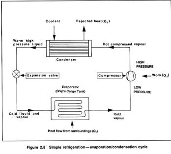 SIMPLE REFRIGERATION / EVAPORATION /
CONDENSATION CYCLE
In considering Figure 2. 8, if:
Q1 is the heat flow rate from the surroundings into the evaporator
Q2 is the heat-rate equivalent of work done on the vapour
by the compressor,
and Q3 is the heat-rate rejected by the condenser
then, if the system were 100 per cent efficient: Q1+Q2=Q3.

Плотность груза.
Основными единицами для подсчета количества груза на борту судна являются его плотность и объём. Используются следующие термины и понятия при определении плотности:
Истинная плотность, или же просто плотность вещества (Density), отображает массу единицы объёма данного вещества в ВАКУУМЕ. Стандартная размерность: кг/л, кг/м3, т /м3.
Реальная плотность (Apparent Density) отображает массу единицы объёма вещества в ВОЗДУХЕ. Стандартная размерность: кг/л, кг/м3, т/м3.
Относительная плотность (Relative Density) выражает отношение массы единицы объёма вещества в вакууме при определенной температуре к массе единицы объёма пресной воды в вакууме, также при определенной температуре. Величина БЕЗРАЗМЕРНАЯ.
Относительная плотность всегда дается с указанием температур, например R. D. 15/15, R. D. 20/4, R. D. 15/20, R. D. 60/60 F и т. д.Ниже приведена таблица истиной и реальной плотности воды при различных стандартных температурах:
Таблица 6. Истинная и реальная плотность воды.
Температура (°С) | Истинная плотность (кг/л) | Реальная плотность (кг/л) |
4 | 1,00000 | 0,99888 |
15 | 0,99913 | 0,99805 |
15,56(60F) | 0,99904 | 0,99796 |
20 | 0,99823 | 0,99717 |
25 | 0,99707 | 0,99604 |
50 | 0,98807 | 0,98702 |
Для пересчета относительной плотности в истинную плотность при определенной температуре необходимо значение относительной плотности умножить на значение плотности воды при указанной температуре.

Расчет газовой фазы груза.
Масса паров в грузовом танке определяется также как и масса жидкой фазы груза - произведением плотности на объём. Самое важное, что необходимо запомнить раз и навсегда, и плотность и объём должны быть определены для одного и того же значения температуры. Для подсчета плотности паров используется основное уравнение газов:
pV = nRT или
m
pV = ¾¾¾ × R × T
Mr
где р – давление абсолютное (Па);
V - объём (л);
Рм_ давление манометрическое
n - число молей;
m - масса (кг);
Mr - молярная масса (кг/моль) ;
R - универсальная газовая постоянная (8,314 Дж/К);
Т - температура в градусах Кельвина.
Многие сюрвейерские организации для подсчета газовой фазы используют расчетное значение плотности газа:
288,15 1,01325 +pM(bar) Mr
r = ¾¾¾¾¾¾ ´ ¾¾¾¾¾¾¾ ´ ¾¾¾¾¾
273,15 +t° C 1,01325 23,6451
эта формула верна для идеальных газов.
Для реальных же газов, формула примет иной вид:
288,15 1,01325 +pM(bar) Mr 1
r = ¾¾¾¾¾¾ ´ ¾¾¾¾¾¾¾ ´ ¾¾¾¾¾ ´ ¾¾
273,15 +t° C 1,01325 23,6451 Z
где Z - фактор сжатия, который при нормальных условиях хранение и перевозки газов очень близок к 1.
Фактор сжатия является функцией от Рr и Тr, где:
Абсолютное давление паров
 Рr=
Рr=
Абсолютное критическое давление
Абсолютная температура паров
Tr = ¾¾¾¾¾¾¾¾¾¾¾¾¾¾¾¾¾
Абсолютная критическая температура
В различных справочных пособиях значения фактора сжатия приводятся в графической форме в зависимости от температуры и давления.
Таблица 12. Таблица переводных коэффициентов.

|
Из за большого объема этот материал размещен на нескольких страницах:
1 2 3 4 5 6 7 8 9 10 11 12 13 |
