

Партнерка на США и Канаду по недвижимости, выплаты в крипто
- 30% recurring commission
- Выплаты в USDT
- Вывод каждую неделю
- Комиссия до 5 лет за каждого referral
GENERAL MANUFACTURING FEATURES
HEAT EXCHANGER (3 smokes revolutions plus flame reversion)
Made of welded stainless steel sheet, sealed tested to meet the current European standards, easy to check for standard cleaning and maintenance operations:
Combustion chamber made of Aisi 430 stainless steel sheet, circular section, of suitable thickness and volume. Wide surface exchanging elements made of low thermal load high quality stainless steel, rhomboid section, granting lower resistance to air cooling and improved thermal efficiency. High quality stainless steel front smokes collector, with wide inspection door for easy checking and cleanings of the exchanger. High quality stainless steel rear smokes collector, which opening is closed by safety disk of suitable features, acting as overpressure valve.Кожух прибора
Кожух прибора, выполнен из окрашенной нержавеющей стали, покрытый специальной пленкой обладающей звуко и тепло изоляциооными свойствами.
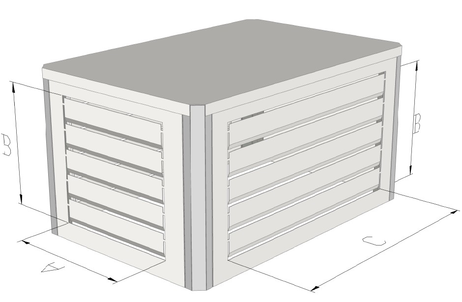
OUTER CASING
No visible panel fixing parts : this gives the machine a new fashionable look, while enabling very easy checking too. The outer casing is made of removable panels made of enamelled stainless steel sheet, delivered with a peel-off film on it, provided with an inner sound & heat proof layer, insulating from the heat coming from exchanger areas, and a protecting sheet.
Циркуляционный блок
Циркуляционный блок выполнен с помощь одного или нескольких центробежных вентиляторов. Могут использоваться вентиляторы, как с внутренним двигателем, так и с ременным приводомЭти вентиляторы обладают большой производительностью по воздуху и низким уровнем шума. Защита вентиляторов обеспечивается защитной сеткой.
В нижеприведенной таблице приведен перечень применимых к воздухонагревательам типа “ATG” вентиляторов и приводных ремней
различных производителей.
VENTILATION UNIT
It is made of one or two centrifugal fans, built-in engine or belt operated - depending on the model. Low noise fans can grant great air delivery, and are protected by mesh safety panels.
In the following table you can find for your reference different pulleys diameters and types of belt, depending on the brand of centrifugal fan used on the "ATG" line generators.
Диаметр привода вентилятора / PULLEYS DIAMETERS | Приводной ремень с трапециевидным сечением / TRAPEZIUM SHAPED BELTS | |||||
Тип / MODEL | двигатель / ENGINE | вентилятор / FAN | MARAZORATI вентилятор / MARZORATI FAN | NICOTRA вентилятор R / NICOTRA FAN | ||
штук / Pes, | тип / Type | штук / Pes, | тип / Type | |||
ATG60 | 90-1A | 170-1A | 1 | A46 | 1 | A46 |
ATG80 | 90-2A | 190-2A | 2 | A60 | 2 | A60 |
ATG 110 | 90-2A | 200-2A | 2 | A62 | 2 | A62 |
ATG 130 | 90-3A | 200-3A | 3 | A66 | 3 | A66 |
ATG 160 | 100-3A | 250-3A | 3 | A68 | 3 | A68 |
ATG 200 | 100-2B | 200-lB | 1 | B50 | 1 | B50 |
200-lB | 1 | B54 | 1 | B54 | ||
ATG 250 | 112-2B | 250-lB | 1 | B58 | 1 | B60 |
250-lB | 1 | B66 | 1 | B62 | ||
ATG 300 | 112-2B | 250-lB | 1 | B62 | 1 | B64 |
250-lB | 1 | B73 | 1 | B72 | ||
ATG 350 | 112-2B | 250-lB | 1 | B54 | 1 | B50 |
112-lB | 250-lB | 2 | B58 | 1 | B58 | |
250-lB | 1 | B59 | ||||
112-2B | 250-lB | 1 | B52 | 1 | B52 | |
ATG400 | 112-lB | 250-lB | 1 | B58 | 1 | B58 |
250-lB | 1 | B62 | 1 | B62 |
ВЫДУВНОЙ КОЛПАК AIR BLOW UNIT
Используется с приборами небольой мощности такими как ATG30-40, ATG60-80 где нет необходимости в распределительном воздушном канале.
For the smaller applianves as ATG30-40 and ATG60-80 there are avalaible perfect designed Air blow elements, which are placed on the top of the appliance.
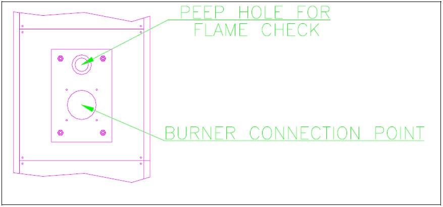
Рампа для горелки
выполнена:
- из нержавеющей стали с отверстием гляделки контроля пламени для газовых и масляных горелок поддувных горелок Подбор производится по таблице на странице 2
BURNING SET
Made of:
- Hooking plate with peep-hole for flame eye
check (Pict.5).
- Gas or gas oil working blown air type burner, certified type to be selected among models at
page 2 (other than the given ones ).

Узел управления вентилятора и теплозащиты, ограничитель предельно допустимой температуры
Теплообменник, вентилятор соединены с датчиками температуры, которые выполняют следующие функции:
- Термостат “Вентилятор” - производит запуск вентилятора при достижении 40 ̊C, затем отключает его при понижении температуры до 40 ̊C. Термостат “Теплозащита” - выключение горелки срабатывает при превышении 80 ̊C. Термостат “Maximum”блокирует весь прибор в случае превышения предельно допустимой температуры. Повторный запуск прибора производится с помощью встроенной в него кнопки, после устранения неполадки в работе прибора.
FAN AND LIMIT CONTROLLER AND MAXIMUM THERMOSTAT
The generator is equipped with fan and limit controller, already mounted and electrically connected, as follows:
- "Fan" thermostat, spring type. It starts up fans when the inside air temperature is about 40°C and makes them stop after the burner stops, and the air temperature is again about 40°C. "Limit" thermostat, spring type. It shuts off the Burner when inside air temperature is getting over 80°C. “Maximum” thermostat, hand reset, liquid expansion type: it definitely stops burner in case of anomalous air overheating. If necessary, you can reset it by hand by depressing the key, however only after detecting and removing the cause for such anomalous behaviour.
Блок управления
На передней панели прибора находится блок управления, степень защиты которого соответсвует „IP56”. Панель управления состоит из (в зависимости от модели): центральный рубильник, сигнальная лампочка хода работы, сигнальная лампочка контроля горелки, гнездо предохранителя, плата, обмотка, термореле, элемент для запаздывания включения, проводка.
.
ELECTRIC BOARD
The generator is supplied with a visible built-in control board placed in the front casing, box type with door, protection degree IP 56, including (depending on the model) : main line switch, working lamp, burner switch with lamp, fuse support, terminal board, coil, meter with thermal relay, delay device and wiring.
Блок световых сигналов
панель управления:
- красный или зеленый световой сигнал, рабочего состояния прибора зеленый световой сигнал рабочего состояния горелки
OPTIC SIGNALLING UNIT
Control board:
- Red or green light, to show correct working. Green switch with light, to show burner connection or cut-out
Патрубок отвода подуктов сгорания
На приборе находится круглой формы (различного диаметра, в зависимости от типа) патрубок отвода продуктов сгорания. Отвод продуктов сгорания осуществляется посредством соединения патрубка с системой дымоудаления, которая должна отвечать следующим требованиям:
- Площадь сечения дымохода не может быть меньше пл. сечения патрубка. Ни в коем случае не допускается сужение дымохода. Элементы дымохода должны быть ровными и иметь гладкую поверхность. В случае, если на каком то участке дымохода используется гофрированная труба необходимо проверить соответствие давления в камере сгорания параметрам, указанным в руководстве горелки. Длина дымохода = min. 0,6 м, max. 3м (колено соответствует 0,8/1м прямой трубы).
OPENING FOR SMOKES EXHAUST
The unit has got a round opening, of variable size diameter depending on the model, to be connected to a metal pipe in the permanent way, to let combustion products exhaust through the flue.
This pipe must be sized as follows:
- It must have wider or same diameter than the opening, withno section reduction. Smooth inside surface. If wrinkled flex pipe was to be used, first make sure that the increased loss of load would not involve "unhealthy" combustion conditions and a too high counterpressure in the combustion chamber. Check working field from the burner manual. Length of flue connecting pipe = min. 0,6 max. 3 line Mts. (the length of a curve is equal to 0,8/1 Mt. of straight pipe
Дымоход

|
Из за большого объема этот материал размещен на нескольких страницах:
1 2 3 4 5 6 7 8 9 10 |
