

Партнерка на США и Канаду по недвижимости, выплаты в крипто
- 30% recurring commission
- Выплаты в USDT
- Вывод каждую неделю
- Комиссия до 5 лет за каждого referral
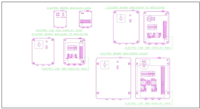
POWER CONNECTIONS
This unit has been manufactured in compliance with CEE 73/23 standard. With models ATG30 - ATG40 current is 220/230 V/AC 50-60 Hz. With remaining models, current is 380/400 V/AC 50-60 Hz. Connection must be made by means ofa "H07- K" cable, with a protective "GSIG" sheath with section suitable to machine absorption. In the table here below you will find for your reference the corresponding machine absorption figures (always check figures directly on unit plate).
Схема принципиальная эктрического соединения см. рис 8.
Connection must be made on terminal board in the control board (Pict.8), strictly following wiring diagram and lettering by terminal board side
Тип ATG30- ATG40
![]()
= заземление в соответствии с предписаниями (зеленый-желтый кабель)
Ph = Фаза (Черный кабель)
N = = Ноль (Голубой кабель)
1 = Ноль на горелку
5 = Фаза на горелку
5-6 = подключение терморегулятора
MODELS ATG 30 & ATG 40
![]()
= Compulsory earth connection (yellow-green wire)
Ph = Active phase connection (brown wire)
N = Neutral phase connection (light blue wire)
1 = Burner connection to neutral phase
5 = Burner connection to line
5-6 = Room thermostat connecti
Тип ATG60-ATG300
![]()
заземление в соответствии с предписаниями (зеленый-желтый кабель)
R-S-T = Фаза (Черный кабель)
N = Ноль (Голубой кабель)
6 = Фаза на горелку
7 = Ноль на горелку
8-9 = подключение терморегулятора
MODELS FROM ATG 60 - TO ATG 300
![]()
= Compulsory earth connection (yellow-green wire)
R-S-T = Active phases connection (black wire)
N = Neutral phase connection (light blue wire)
6 = Burner connection to line
7 = Burner connection to neutral phase
8-9 = Room thermostat connection.
Тип ATG350-ATG400
![]()
= заземление в соответствии с предписаниями (зеленый-желтый кабель)
R-S-T = Фаза (Черный кабель)
N = Ноль (Голубой кабель)
7-8-9 = Фаза на горелку
10 = Ноль на горелку
15-16 = подключение терморегулятора
MODELS FROM ATG 350 TO G 400
![]()
= Compulsory earth connection (yellow-green wire)
R-S-T = Active phases connection (black wire)
N = Neutral phase connection (light blue wire)
7-8-9 = Burner connection to line
10 = Burner connection to neutral phase
15-16 = Roomthermostat connection.
![]()
![]()
Прибор должен подключаться к электрической сети только, через магнитный пускатель с термо защитой.
Электроединение горелки выполняется в соответствии с ее руководством.
We recommend that connection is made preferably by in the permanent way, by means of a magneto/thermal switch of suitable power
As to burner's connection, please refer to its manual.
ПОДКЛЮЧЕНИЕ ТЕРМОРЕГУЛЯТОРА
(ОПЦИЯ)
ROOM THERMOSTAT CONNECTION
(OPTION ONLY)
Соединение терморегулятора с прибором производится в сотвествии с рис. 5. Место установки для датчика температуры должно быть выбрано так, чтобы он не был подвержен прямому нагреванию прибором.
Connection must be made on terminal board in the control board (Pict. S), strictly following wiring diagram and lettering printed on the terminal board side. See power connection. Sensor has to be placed in a convenient position (1,5 to 1,7 Mts. from the floor) so to feel always medium temperature.
ПОДБОР ГОРЕЛКИ
Горелка подбирается таким образом, что бы ее размеры и параметры соответствовали с воздухонагревателем. В любом случае сопоставте данные приведенные в руководстве по эксплуатации горелки с нижеприведенной таблицей.
CHOOSING THE BURNER
To ensure proper unit working, burner's flame pipe must be at least as long as the depth of the combustion chamber mouth and the pressure value for the available combustion air must be higher than take-off and operating pressure values. To make choice easier, check table below and pressuresation diagram as given in burner handbook.
MODEL | ATG30 | ATG40 | ATG60 | ATG80 | ATGIlO | ATG130 | ATG160 | ATG200 | ATG250 | ATG300 | ATG350 | ATG400 |
COUNTERPRESSURE IN THE COMBUSTION CHAMBER Pa | 0 | 15 | 22 | 30 | 35 | 41 | 50 | 62 | 78 | 112 | 132 | 150 |
CAPACITY in kW | 34 | 46 | 69 | 93 | 127 | 151 | 186 | 232 | 290 | 348 | 407 | 465 |
![]()
Внимание: Настройка, пуско-наладка горелки должна выполняться квалифицированным сотрудником уполномоченной организации. Производитель не несет ответственности за убытки, возникшие по причине неправильной установки или настройки горелки.
![]()
WARNING: The correct adjusting of the burner thermal capacity will depend on whether this has been made by a qualified
installing operator or not. The manufacturer will never be responsible for any direct damage resulting from wrong installing or adjusting.
ТИП ATG/30-AS и ATG/40
ATG/60-TУL ATG/400-AS MODELLEKIG
MODELS ATG/30 & ATG/40
FROM MODEL ATG/60 TO MODEL ATG/400
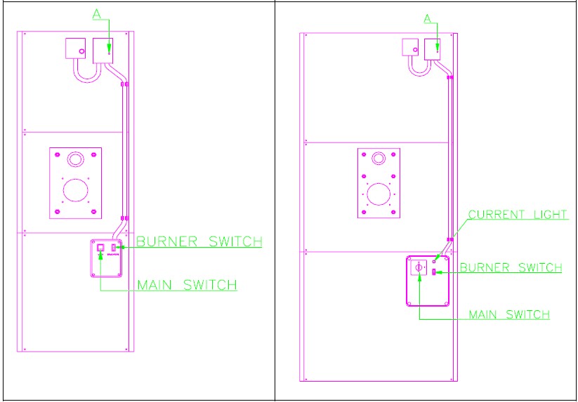
Пуско – наладка газовой горелки
Перед первым включением горелки необходимо выполнить следующие указания:
- Убедитесь в том, что центральный рубильник включен. Откройте газовый кран для продувки системы (см. руководство к горелке) Включите электропитание прибора. На приборах ATG/60 до ATG/400 запуск вентилятора производится нажатием на кнопку «А» - белого цвета, находящуюся на двойном терстате прибора (см. рис. 9). Убедитесь в том, что направление вращения вентилятора совпадает с указательной стрелкой вращения. В случае, если направление не соответствует, необходимо поменять фазу и повторить запуск. Включатель горелки установите в положение I (см. рис. 9), после чего загорится котрольная лампочка горелки. Удалите блокираторы (см. руководство к горелке) задайте для горелки необходимую Вам мощность (см. руководство к горелке) Убедитесь, что пропускная способность газопровода обеспечит необходимое для работы горелки к-во газа. После завершения наладки, необходимо зафиксировать настройки (напр.:каплей краски или воска, и т. п…)
GAS BURNER FIRST START
To start the burner the first time, just do as follows:
- Make sure that main switch on control board is activated. Open gas tap and let air leak out from pipe if necessary (see burner instrnctions). Give voltage to appliance. With models ATG/60 to ATG/400 pull white "A" knob on bi-thermostat (Pict. 9). This will start up fans. Check that rotating way is same as required by plate (see arrow) on fan fairing. If different, put main switch off, reverse a phase on control board, put main switch on again and check rotating way again as told before. Bring burner switch to I position (Pict. 9), led on; in this way you're giving voltage to burner (tum burner switches on, if any). Remove blockages if any (see burner handbook). Adjust burner to required capacity (see bnmer handbook). Make sure that gas consumption quantity as you can read from counter does corresponding to the figure stated in the burner handbook and to the nominal thermal capacity as stated by the handbook or by the plate on the unit. After having made all adjustments, the installer must duly seal the adjusting gears (example: paint drop).
![]()
![]()
Внимание: Желаемая температура помещения задается на терморегуляторе и ни в коем случае не на двойном термостате.
PLEASE NOTE: ROOM TEMPERATURE CAN BE ONLY ADJUSTED ON THE ROOM THERMOSTAT, NOT ON THE APPLIANCE BI-THERMOSTAT.
УСТРАНЕНИЕ НЕПОЛАДОК
МЕТОДЫ УСТРАНЕНИЯ НЕПОЛАДОК
При выходе из строя прибора необходимо проверить следующее.
- соответствие напряжение питанияв эл. сети не превышает ли падение напряжения +10% / -15% состояние предохранителей. встроенный двигатель должен быть в выключенном состоянии достаточное кол-во топлива соответствие давления тех. параметрам прибора
В ниже приведенной таблице указаны возможные неисправности и методы их устранения
TROUBLE-SHOOTING
MALFUNCTIONS - CAUSES & REMEDIES
In case of malfunctions in the hot air generator, first check the following points:
- Electric power must be connected. Should a rush of current occur, this mustn't exceed + 10% / -15%. Fuses must be in order. Built-in engines thermal protections must be disconnected. There must be enough gas or gas oil available. Gas or gas oil pressure and capacity must be exactly as stated in the technical data.
Here below now please find the following troubleshooting list, showing main malfunctions you might experience with this unit, while you'll be finding also the reasons and remedies to restore the correct performance.

|
Из за большого объема этот материал размещен на нескольких страницах:
1 2 3 4 5 6 7 8 9 10 |
