
Партнерка на США и Канаду по недвижимости, выплаты в крипто
- 30% recurring commission
- Выплаты в USDT
- Вывод каждую неделю
- Комиссия до 5 лет за каждого referral
Consequently, the structure consists from 4 independent groups for each basic driven direction: forward, rearward, left, and right (Fig 7).
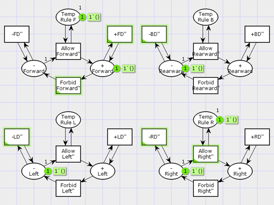
Fig. 7 The rules structure for the 4 directions of the Rule PN.
There is the same rule pattern for each direction. This pattern contains 3 states by the example of the forward direction (top right net on Fig. 7):
· Temp Rule F – determines the temporary or regular prohibition for driving to this direction.
· -Forward – no passage for the current direction
· +Forward – the passage is permitted for the current direction
The states are connected with the next transitions:
· Allow Forward” – activates the legal drive on this direction
· Forbid Forward” – no passage for the current direction
· +FD” – enables the permission for the car on this direction
· –FD” – enables the prohibition for the car on this direction
Transitions Allow and Forbid are synchronized with environment’s transitions. During simulation they can be fired by traffic-light events or by road users. Transitions with prefix “+” and “–” in their titles are synchronized with proper transitions in the car net, when car token enters into the road sector state (Fig. 6). For example, if on the current sector the turn right is restricted, this means that when car token get into the system state with this rule token, the transition –RD” fires in the rule net and in the car net, hence the horizontal synchronization is launched.
There is the possible instance of the initial marking on Fig. 7. The state with name Temp Rule can contain the token if the permission to drive is temporary. It depends on the road situation and defines on the modeling stage. In this case the transition with Allow will be enabled and can be fired to activate the permission for driving on the given direction by “+” transition. The state Temp Rule can be marked if there is the traffic light on the current road sector. When it has the green light the Allow Forward” transition would fire and after that the synchronous +FD” also would fire for the car net. When the traffic light would have the red light the Forbid Forward” transition would fire to forbid drive in forward direction. According to the designed model there is the prohibition to drive to any direction by default. So, when the state Temp Rule has no token only Forbid transition would be enabled. This situation can be happened with restricted sign, which supposed constant rule for the given direction. In that case only transitions with prefix “–” is enabled and have synchronization with car net.
Road Priority Rules Structure:
To check the order of passage through the junction according to priority rules it is necessary to analyze the oncoming traffic. The priority of each way on the junction and the further driving direction of each car on this junction should be determined. It has an influence on the next action for each participant of traffic. The analyses of all possible cases with drivers having different priorities of the road, is needed for creating verification model. Accordingly, the patterns of the driver’s behavior should be determined depending on the traffic road rules for the cars coming from the left, front and right side. The results are shown on the following tables I, II, III.
TABLE 1
Priority For The Left Car
The Left Car Next Direction | The Driver Next Way Direction | |||||||
Left | Forward | Right | ||||||
Priority Driver’s Road | ||||||||
Min | Maj | Min | Maj | Min | Maj | |||
Left | Priority Left Car’s Road | Min | + | + | + | + | + | + |
Maj | - | - | - | |||||
Forward | Min | + | + | + | + | + | + | |
Maj | - | - | - | |||||
Right | Min | + | + | + | ||||
Maj |
Min is a minor and Maj is a major road for the current car
(+) – the driver don’t make way and has a priority over oncoming car
(-) – the driver should make way and hasn’t a priority over oncoming car
TABLE 2
Priority For The Front Car
The Front Car Next Direction | The Driver Next Way Direction | |||||||
Left | Forward | Right | ||||||
Priority Driver’s Road | ||||||||
Min | Maj | Min | Maj | Min | Maj | |||
Left | Priority Front Car Road | Min | + | + | + | + | + | + |
Maj | - | - | - | |||||
Forward | Min | - | + | + | + | |||
Maj | - | |||||||
Right | Min | - | + | + | + | |||
Maj | - |
Min is a minor and Maj is a major road for the current car
(+) – the driver don’t make way and has a priority over oncoming car
(-) – the driver should make way and hasn’t a priority over oncoming car
TABLE 3
Priority For The Right Car
The Right Car Next Direction | The Driver Next Way Direction | ||||||
Left | Forward | Right | |||||
Priority Driver’s Road | |||||||
Min | Maj | Min | Maj | Min | Maj | ||
Left | Priority Right Car’s Road | Min | - | + | - | + | + |
Maj | - | - | |||||
Forward | Min | - | + | - | + | + | |
Maj | - | - | |||||
Right | Min | - | + | - | + | + | |
Maj | - | - |
Min is a minor and Maj is a major road for the current car
(+) – the driver don’t make way and has a priority over oncoming car
(-) – the driver should make way and hasn’t a priority over oncoming car
There is the comparison of current cars’ road priority and their next driving direction to determine is the driver should make way for oncoming car or not. The next direction is determined relatively to each driver’s point of view. In case when the drivers have the same road priority, the decision is based on the right-hand rule.
Based on these tables the patterns of the junction passage are defined. The main concluded feature is that for the driver there is no value in which next direction the cars from the left and right sides will pass the junction. It is represented by the equal Left and Forward rows in Table I. and by every identical row in Table III. For these cases only the priority of the roads is important. The row Right on Table I. shows, that the entering on the junction driver will not have any obstacles and don’t make way, if the driver of the left car wants to turn right.
There is another situation for the oncoming front car. It has two significant groups of directions for road code verification. The first includes rows Forward and Right in Table II, which are equal. And the second consists from Left row. As a result, the model should contain distinction between the next drive directions for the front car.
The next ways of the drivers are defined by events of the turning signals. The driver turns on the proper signal in case he wants to make the desired turn, and he does not turn on any signal in case to pass directly through the junction. According to significant cases when the driver should give way for the other cars the verification model is designed. There is the resulting road priority net model on Fig. 8.
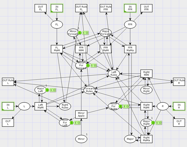
Fig. 8 The PN structure of priority rules for the cars of left (L), front (FL, FFR) and right (R) direction from the driver point of view.
The net contains the next states:
· States related to the left car:
o L – there is a car on the left road
o Minor Left – is marked if the left road has minor priority for the driver
o Major Left – is marked if the left road had major priority for the driver
o Minor For Left – the driver has minor priority relative to the left road

|
Из за большого объема этот материал размещен на нескольких страницах:
1 2 3 4 5 6 |
