

Партнерка на США и Канаду по недвижимости, выплаты в крипто
- 30% recurring commission
- Выплаты в USDT
- Вывод каждую неделю
- Комиссия до 5 лет за каждого referral
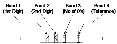
The tolerance band is a single band near one end of the resistor and is normally gold or silver. A gold band indicates a tolerance of ±5%, while a silver band indicates ±10%. If there is no fourth band then the tolerance will be ±20%.
The value of the resistor (in ohms) can be worked out by looking at the three other coloured bands and using the colour code table.
|
Colour | Value | Colour | Value |
Black | 0 | Green | 5 |
Brown | 1 | Blue | 6 |
Red | 2 | Violet | 7 |
Orange | 3 | Grey | 8 |
Yellow | 4 | White | 9 |
Examples:
1.
|
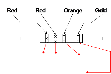
Value = 2 2 (three 0’s) Ω
= 2 2 000 Ω = 22kΩ
Tolerance = ± 5%
2.
|

Value = 4 7 00000 Ω = 4700kΩ = 4.7MΩ
Tolerance = ± 20%
3.
|

Value = 1 2 (no 0’s) Ω = 12Ω
Tolerance = ± 10%
plete the following diagrams by showing the colour code required for the following resistors:
a) 75kΩ, ±5% resistor.
 75kΩ = 75000Ω = 7 5 000 ±5%
|

b) 18Ω ±10% resistor. (1 8 _ ±10%)
|

c) 360Ω (±5%) resistor. (3 6 0 ±5%)
|

d) 2.4MΩ (±5%) resistor. (2 4 00000 ±5%)
|

Printed value
Equipment manufacturers’ circuit diagrams often use the following code for indicating resistor values. The letters give multiples and the position of the decimal point.
Examples:
Marking | Resistor Value |
R33 | 0.33Ω |
3R3 | 3.3Ω |
33R | 33Ω |
330R | 330Ω |
3k3 | 3.3kΩ |
33k | 33kΩ |
3M3 | 3.3MΩ |
Self Assessment Test.
1. Use the colour code to find the value of the resistors shown below.
a.
|

...................................................................................................................
b.
|

...................................................................................................................
c. What is the highest value that the resistor (b) is likely to have?
........................................................................................................................................
........................................................................................................................................
d. Using the resistor printed code – what are the values of the following resistors.
i) 470R..................
ii) 2k2 ..................
iii) 5M6 ..................
plete the following diagrams by showing the colour code required for the following resistors:
i) 270 Ω, ±5% resistor.
|
ii) 10kΩ ±10% resistor.
|
iii) 3.9kΩ ±10% resistor.
|
iv) 8.2MΩ ±5% resistor.
|
Self Assessment Test
1. a. 27000Ω = 27kΩ ±5% b. 56Ω ±10%
c.  d. i) 470Ω; ii) 2.2kΩ iii) 5.6MΩ
2. i) Red Violet Brown Gold.
ii) Brown Black Orange Silver.
iii) Orange White Red Silver.
iv) Grey Red Green Gold
Calculating the value of a current limiting resistor
Suppose we want to operate a 2.5V, 0.25A bulb on a 6V supply.
For the bulb to operate at its specified brightness, it must have 2.5V dropped across it. The difference between this voltage and the supply voltage can be dropped across a series resistor. The resistor value selected should allow 0.25A to flow through it when there is a voltage of (6-2.5)V across it.
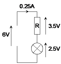
Applying Ohm’s Law to the resistor:
 so
so 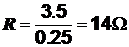
There are no 14Ω resistors available in the E24 series. This provides us with a dilemma since we have to choose between a 13Ω, or a 15Ω resistor. Let us look at the effect of each.
If we choose a 13Ω resistor, this will mean that the circuit resistance will be less than we needed. A larger current than expected will flow and will therefore put a greater strain on the bulb, and this will reduce its operating life time.
If we choose a 15Ω resistor, this will mean that the circuit resistance is slightly higher than that required, which will reduce the current flowing below 0.25A. The result will be a bulb operating at slightly less than full brightness, but within its maximum value.
The most suitable preferred value resistor is this case would be 15Ω.
Resistors in series
The following 2 circuits have been set up on a circuit simulator.
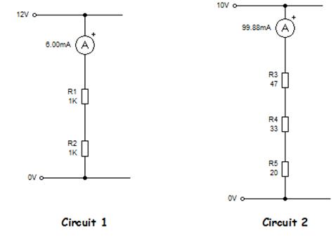
Look at Circuit 1 and you will see that the ammeter reading is 6.00mA. We can apply Ohm’s Law to the circuit to find the total resistance of the circuit.

If we add up the values of R1 and R2 from Circuit 1 we get
R1 + R2 = 1kΩ + 1kΩ = 2kΩ
Which is exactly the same answer as we got using Ohm’s Law?
Look at Circuit 2 and you will see that the ammeter reading is 99.88mA. We can apply Ohm’s Law to this circuit to find

If we add up the values of R3, R4 and R5 from Circuit 2 we get
R3 + R4 + R5 = 47Ω + 33Ω + 20Ω = 100W.
Which is nearly but not exactly the same answer as we got using Ohm’s Law?
The difference in this case of 0.12W is due to very small rounding errors that occur when the simulator is displaying current flow.
So we can see that the total or effective resistance Rs of resistors in series is given by the general equation:
Rs = R1 + R2 + R3 + ..........
Therefore:
if R1 = 10Ω and R2 = 40Ω, then Rs = 10 + 40 = 50Ω.
if R1 = 15kΩ, R2 = 25kΩ, and R3 = 75kΩ
then Rs = 15k + 25k+ 75k = 115kΩ.
Resistors in Parallel
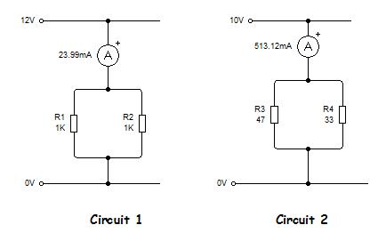
Look at Circuit 1 and you will see that the ammeter reading is 23.99mA. We can apply Ohm’s Law to the circuit to find the total resistance of the circuit.

Look at Circuit 2 and you will see that the ammeter reading is 513.12mA. We can apply Ohm’s Law to this circuit to find

There does not seem to be an obvious relationship between the effective resistances and the resistor values used, other than the effective resistance in each case is smaller than the individual parallel resistor values.

|
Из за большого объема этот материал размещен на нескольких страницах:
1 2 3 4 5 6 7 8 9 |
