

Партнерка на США и Канаду по недвижимости, выплаты в крипто
- 30% recurring commission
- Выплаты в USDT
- Вывод каждую неделю
- Комиссия до 5 лет за каждого referral
.........................................................................
.........................................................................
.........................................................................
[4]
1.4.2 – Light Dependent Resistors
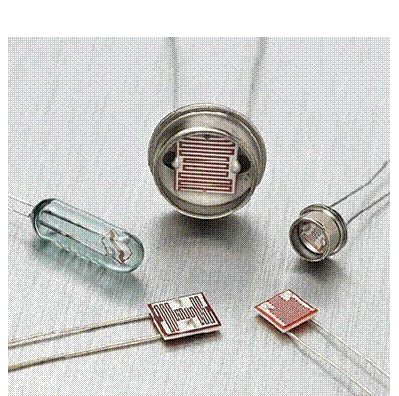
A Light Dependent Resistor or LDR consists of a cadmium sulphide track set out on an insulator base. The resistance of the track depends upon the intensity of light which falls upon it. You can see the track through the transparent window on the top of the unit.
The symbol for an LDR is as follows:

The LDR comes in a variety of different packages as shown below:
 |
The resistance characteristic for the LDR is shown at the top of the following page:
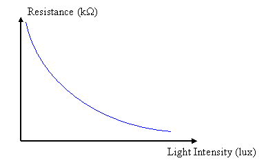
The light intensity is measured in a unit called ‘lux’, but we can see from the characteristic curve that the resistance of the LDR falls as light intensity increases. The decrease in resistance is non-linear, the resistance falls rapidly at first and then less quickly as the intensity of light increases.
The type of LDR provided in the Alpha kit is a type ORP12. The Data Sheet for the device quotes a resistance of several MΩ in total darkness, falling to about 1kΩ in bright light.
One disadvantage of LDRs is that they respond rather slowly to changes in light intensity. The ORP12 takes about 120 ms to complete its change in resistance when light level changes from darkness to bright light. This is a long time in terms of electronic switching circuits!
1.4.3 – NTC Thermistors
The thermistor is a two leaded component that changes its resistance in response to a change in temperature. The symbol for a thermistor is shown below:

The ‘-t°’ alongside the symbol indicates that this is a negative temperature coefficient (or n. t.c.) thermistor, which simply means that the resistance of the thermistor decreases as temperature increases.
A positive temperature coefficient (p. t.c.) thermistor does exist where the resistance increases as temperature increases, but these will not be examined as part of this course. The symbol is the same, but just has a ‘+t°’ alongside it should you see this in any project books you may look at.
The characteristic curve for a thermistor, therefore looks like this.
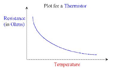
Once again we can see that the response is non-linear, i. e. resistance falls quicker at the start and then the rate of decrease in resistance slows down as higher temperatures are reached.
Thermistors come in many different physical packages as shown by the diagram below:
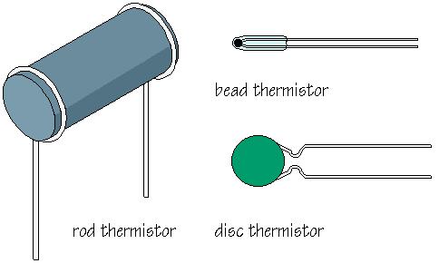
Irrespective of the package style the behaviour of all of these thermistors is the same, as temperature rises the resistance of the thermistor falls.
The change in package style does however affect the response time of the thermistors, the ‘rod’ style thermistor is large and bulky and has the slowest response time, whilst the tiny ‘glass bead’ style has the fastest response.
Depending on the application different styles of package can be selected but it is important to remember that from circuit design point of view the package is not important as long as we know the range of resistance the thermistor has over the temperature range that it will be used.
A typical data sheet for a thermistor is shown below:
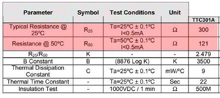 |
The first two rows in this table show that at 25°C the resistance is 300Ω, and at 50°C the resistance has fallen to 121Ω. All thermistors are different so it is important to check their data sheets to determine their characteristics so that a suitable circuit can be designed to use them effectively.
We will investigate more about how the LDR and Thermistor are used to make sensing circuits in our next Topic 1.5. For now it is sufficient for you to be able to recognise their symbol and describe their characteristic.
1.4.4 – Switches
A mechanical switch is used to physically break the electrical connection between two points in the circuit, and then allows us to reconnect these parts safely, without risk of electrical shock, particularly useful when dealing with high voltages and currents.
There are many different types of switches as you will find out in the practical assignment, however we will look at the main basic groups now and some of the jargon which is associated with different types of switches.
a) Switch Contacts
The contact arrangement of switches is classified in terms of:-
Poles - The moving part of the switch which is pivoted.
Throws - The part of the switch which is fixed and makes contact with the moving part of the pole.
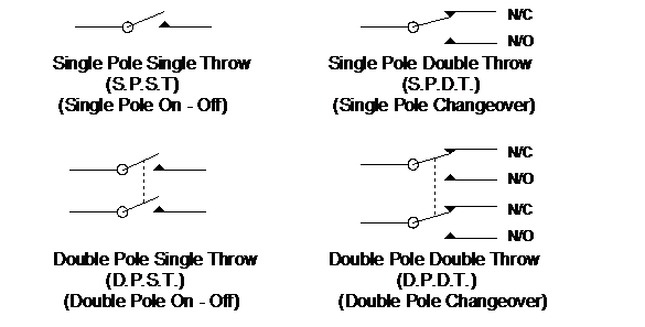
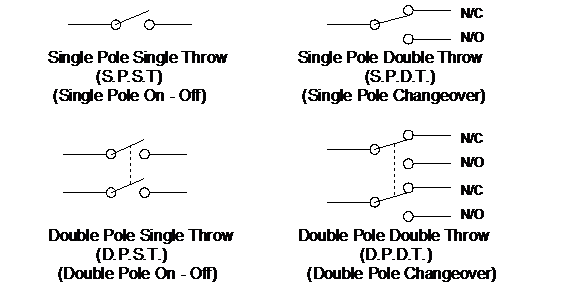 The following diagram gives the circuit symbol for the four main categories of switch contact arrangements. There are others but these are normally restricted to specific applications.
The dotted line indicates that the two poles are mechanically connected (or ganged) but are not electrically connected.
With changeover switches the contacts may also be called, or marked N/O or N/C, these stand for Normally Open, or Normally Closed. i. e. the N/O contacts are those which are not connected together when the switch is in the unoperated (off) position. These contacts are made when the switch is operated. Similarly the N/C contacts are connected when the switch is unoperated (off) and the contact is broken when the switch is operated.
b) Uses of switches
i) SPST switches are often used to switch on and off low voltage electronic circuits
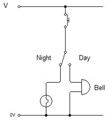 ii) A SPDT switch is useful when selecting one of two alternative circuits or to operate a device from one of two positions as is commonly used for staircase lighting.
Another example of an use for a
SPDT switch is a door bell which
can be switched off at night and
replaced with a bulb so as not to
disturb a sleeping child.
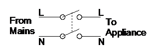
iii) A DPST switch is really two separate switches controlled by one lever. A typical use is in mains appliances to disconnect both the live and neutral wires as a safety precaution.
|
iv) A DPDT switch is often used to reverse the direction of a motor.
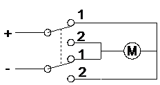
When the contacts are switched from
position 1 to 2 the current flows in the
opposite direction through the motor
and hence reverses the direction of the
motor.
Note: The arrangement of relay contacts is also described in terms of poles and throws, but the symbols are different to those of a mechanical switch, so that they can be identified on circuit diagrams, as shown below:
c. Switch types
i) Press switches are used for momentary contact and are spring loaded. A common example of a press switch is on a door bell, or keyboard.
|
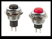
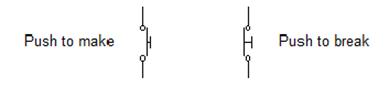
The press switch is a variation of the S. P.S. T. switch and is available in two variants: Push to make and Push to break.
Symbols are as follows:
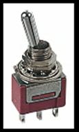
ii) Toggle switches are two position switches and are normally used as on/off switches.
|
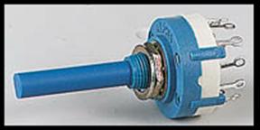
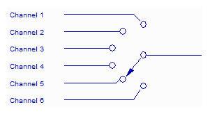
iii) Rotary switches are multiway switches and are used only in very specific applications. Each of several channels may be selected by turning a spindle. It is not unusual to have up to twelve separate channels for selection from just one pole.
|
The symbol for a rotary switch is shown below.
|
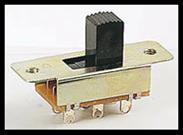
iv) Slide switches are inexpensive and are found mainly in low voltage circuits. They are useful for setting the logic levels of gates high or low.
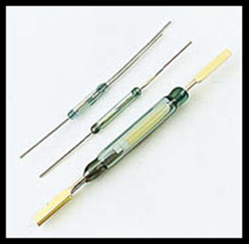
v) Reed switches are made from two pieces of metal sealed inside a glass case. When a magnet is brought close to the glass the two contacts inside join and complete the circuit. These switches are particularly useful in burglar alarm circuits, when the switch is mounted in a door frame and a magnet inserted into the actual door. When the door is closed the circuit is complete, but when opened and the magnet moves away the contacts open causing a break in the circuit, hence triggering the alarm.
 |
vi) Microswitches are very sensitive push switches which require a very low operating force over a very small distance. They are ideal for sensing very small movements.

|
Из за большого объема этот материал размещен на нескольких страницах:
1 2 3 4 5 6 7 8 9 |
