

Партнерка на США и Канаду по недвижимости, выплаты в крипто
- 30% recurring commission
- Выплаты в USDT
- Вывод каждую неделю
- Комиссия до 5 лет за каждого referral
|
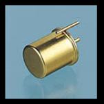
vii) Tilt switches are formed by sealing two contacts in a metal can with a small amount of mercury. The switch is positioned so that when a video for example is in its normal position the mercury lies across the two contacts, completing the circuit. If the video is lifted and tilted then the mercury will run off the contacts as it is a liquid and break the circuit triggering an alarm.
|
Homework Questions 3
Answer all questions in the spaces provided; continue on a separate piece of paper if required.
1. Draw the electrical circuit symbol for a light dependent resistor.
[1]
2. Describe the operation of the LDR.
........................................................................................................................................
........................................................................................................................................
........................................................................................................................................
........................................................................................................................................
[2]
3. Draw the electrical circuit symbol for a thermistor.
[1]
4. Describe the operation of the thermistor.
........................................................................................................................................
........................................................................................................................................
........................................................................................................................................
........................................................................................................................................
[2]
5. What are mechanical switches used for in modern electronic circuits?
........................................................................................................................................
........................................................................................................................................
[1]
6. Give a brief description of the key uses of the following types of switches.
i) SPST.
........................................................................................................................................
........................................................................................................................................
........................................................................................................................................
[1]
ii) SPDT.
........................................................................................................................................
........................................................................................................................................
........................................................................................................................................
[2]
iii) DPDT.
........................................................................................................................................
........................................................................................................................................
........................................................................................................................................
[2]
7. Draw the circuit symbols for (i) Push to Make switch, and (ii) Push to Break Switch.
i) ii)
[2]
iii) What is the key difference between these two switches?
.............................................................................................................................
.............................................................................................................................
[1]
8. Describe a situation where you might require the use of a Reed Switch.
........................................................................................................................................
........................................................................................................................................
........................................................................................................................................
[1]
9. Describe a situation where you might require the use of a Tilt Switch.
........................................................................................................................................
........................................................................................................................................
........................................................................................................................................
[1]
10. i) Draw a circuit diagram to show how a 1kΩ resistor and a SPST switch can be connected to a 12V supply, so that when the switch is open, the output voltage is 12V, and when the switch is closed the output voltage is 0V.
[2]
ii) Modify your circuit diagram to show how the same components and a 9V power supply may be used to provide an output voltage of 0V when the switch is open, and an output voltage of 9V, when the switch is closed.
[1]
Solutions to Homework Exercises.
Homework Questions 1
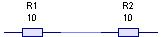
1. (a)
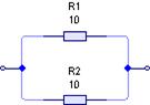
(b)
[2]
2. (a) 1A.
[1]
(b) 1A.
[1]
(c) 
[2]
(d) 
[2]
(e) Vsupply = V3Ω + V6Ω = 3 + 6 = 9V
[1]
3. (a) the current in the 3Ω resistor will be twice as much as that in the 6Ω resistor and total current is 6A. Therefore current in 3Ω must be 4A.
[1]
(b) the current in the 6Ω resistor will be half that in the 3Ω resistor and total current is 6A. Therefore current in 6Ω must be 2A.
[1]
(c) 
[2]
(d) 
[2]
(e) Vsupply = V3Ω = V6Ω = 12V {parallel circuit}
[1]
4.
(a) 
[1]
(b) 
[1]
(c) 
[1]
(d) 6.2kW
[1]
Homework Questions 2
1. i) The lamp will blow.
ii) The lamp could be successfully connected into the circuit if a resistor of suitable vale were added into the circuit in series with the lamp so that some of the battery voltage was dropped across the resistor.
2. i) ii)
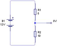
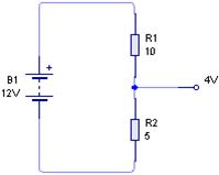
3.

4. Either
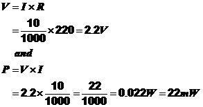
Or
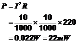
5. Advantages: Any two from : Very Accurate, Value does not change when resistor heats up, Can dissipate high powers.
Disadvantages: They are bulky and heavy, rather expensive.
6. Advantages: Any two from : Easy to manufacture, Cheap, Good Tolerance ±5%
Disadvantage: Poor temperature stability.
7. i) Tolerance.
ii) Wattage.
iii) Stability. (in any order)
8. i) 220Ω, ±5%
ii) 9100Ω or 9.1kΩ, ±10%
iii) 10000Ω or 10kΩ, ±5%
iv) 68Ω, ±5%
9. i) Yellow, Violet, Red, Silver.
ii) Brown, Black, Yellow, Gold.
iii) Orange, Orange, Orange.
iv) Orange, White, Black, Gold.
10. i) 47Ω.
ii) 2.7kΩ.
iii) 1.8MΩ.
11. i) 10k
ii) 3k3
iii) 5M6
iv) 10R
|
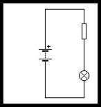
12. i)
ii) If the power supply is 9V and the lamp is rated at 3.5V, 5.5V must be dropped across the resistor. Since it is a series circuit the same current which flows through the lamp must flow through the resistor, so I = 0.03A. Therefore, applying Ohms law to the resistor gives
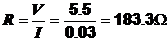
iii) Looking at the E24 series of resistors will show that there is no 183.3Ω resistor available. We have a choice between 180Ω or 200Ω. If we use the 180Ω resistor however we will be putting less resistance in the circuit than required, this will cause an increase in current, which will reduce the life of the lamp. Therefore it would be more appropriate to use the 200Ω resistor, as this will ensure that the current is kept slightly below the maximum rated value of the lamp, hence preserving battery life.
13. 5% of 1000Ω is given by the following:

The minimum value is therefore given by 1000Ω - 50Ω = 950Ω.
The maximum value is therefore given by 1000Ω + 50Ω = 1050Ω.

|
Из за большого объема этот материал размещен на нескольких страницах:
1 2 3 4 5 6 7 8 9 |
