

Партнерка на США и Канаду по недвижимости, выплаты в крипто
- 30% recurring commission
- Выплаты в USDT
- Вывод каждую неделю
- Комиссия до 5 лет за каждого referral
14. i)
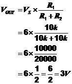
ii)
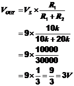
iii)
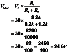
Homework Questions 3
 1.
1.
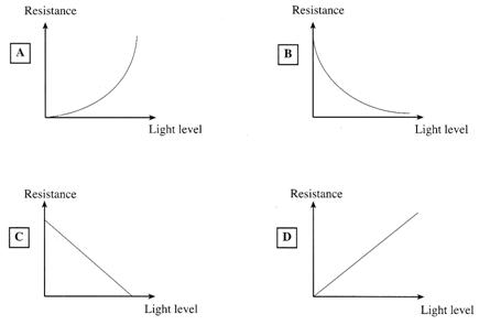
2. The resistance of an LDR changes depending on how much light falls onto the window of the package. The more light that falls on the window the lower the resistance of the LDR. Resistance can vary from approximately 500Ω in bright light to several MΩ in darkness.
3.

4. The resistance of the thermistor is dependent upon it’s temperature. The resistance of the thermistor falls as the temperature rises. The range of resistance will vary greatly depending on the type of thermistor used, but is typically from approximately 100kΩ when cold to 500Ω when hot (100°C)
5. Mechanical switches are used to connect and disconnect different parts of an electrical circuit without risk of electrical shock to the user. Switches will be found on nearly all items of electrical equipment. Their main use is to disconnect the power supply from the circuit, either to allow work to be carried out on the equipment or to preserve battery life in the case of battery operated equipment.
6. i) SPST, switches are sometimes referred to as on/off switches. They have only two contacts, and are capable of only making or breaking a single connection in a circuit. Main uses are for switching battery operated equipment on and off.
ii) SPDT, switches are sometimes referred to as changeover switches. They have one input terminal but two output terminals. Their main use is in changing the output path of current, for example, this type of switch may be used to change the path of current from a buzzer to a lamp on a doorbell, so that the buzzer can be switched off at night and the light switched on by the bell push on the door instead, so preventing waking up small children that might be asleep.
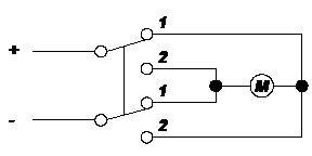
iii) DPDT, switches are really two SPDT switches together, but operated by the same lever. The main use of this type of switch is for reversing electrical motors, as shown in the following diagram.
|
7. i) ii)

iii) Both of these switches are momentary action switches. The push to make is normally open, i. e. the circuit is broken and is only connected when the push button is pressed. The push to break switch however is normally closed, i. e. the circuit is connected until the push button is pressed when the circuit is then broken.
8. Reed switches are operated by a magnet, and as such are particularly useful for burglar alarm applications where the magnet is fixed to the door, and the reed switch to the door frame. When the door is opened the magnet moves away from the reed switch and breaks the circuit, and setting off the alarm.
9. A tilt switch as its name suggests operates when it is moved to an angle. It’s applications are typically in tractors, cranes and heavy machinery which operate on slopes or at unusual angles to warn the driver that his machine is close to the point of toppling over so that precautionary measures can be taken.
10. i)
|
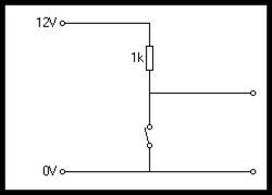
ii)
|
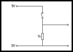
Now for some examination style questions.
Examination Style Questions
Note: For all examinations the resistor colour code, and voltage divider formula is provided on Page 2, the pupil information page of each examination paper. They are reproduced here for use with the following questions.
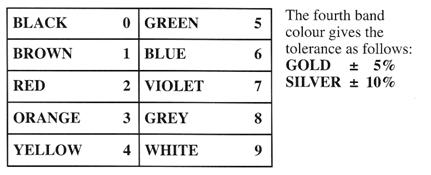
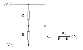
1. The resistor colour code is given in the information sheet on page 2.
(a) Use the information to work out the colour code for a 680Ω resistor.
Write the colours in the correct spaces on the diagram below.
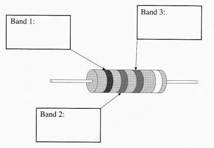
[3]
(b) Use the colour code to work out the resistance of the following resistor.
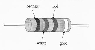
Resistance in ohms = ..................................
[2]
(c) A voltage divider is set up as shown in the following diagram.
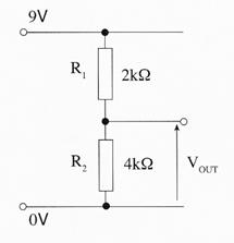
(i) What is the combined resistance of R1 and R2?
......................................................................................................................................
(ii) Use the equation given in the information sheet on Page 2 to calculate the output voltage VOUT.
......................................................................................................................................
......................................................................................................................................
[2]
2. The following diagram shows 3 resistors arranged as a voltage divider:-
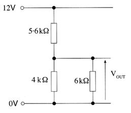
(a) Use the information sheet on page 2 to help you calculate the combined resistance of the 4kΩ and 6kΩ resistors.
..............................................................................................................................................
..............................................................................................................................................
[1]
(b) Calculate the output voltage VOUT.
..............................................................................................................................................
..............................................................................................................................................
[2]
3. Which of the following graphs A, B, C or D best shows the way in which the resistance of an LDR depends on the light level?
 |
Answer = ............................. [1]
4. Here is a diagram of a 560Ω resistor with a 5% tolerance.
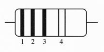
Complete the following table.
Resistor Value | Colour of Band 1 | Colour of Band 2 | Colour of Band 3 | Colour of Band 4 |
560Ω |
[4]
5. The resistor colour code is given in the information sheet on page 2.
Here is a diagram of a resistor.
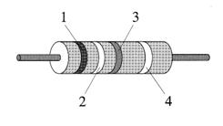
The table shows the colours of the bands on a resistor.
Band 1 | Band 2 | Band 3 | Band 4 |
Orange | White | Orange | Silver |
(a) (i) Use the colour code to work out the value of the resistor.
Resistance in ohms = ................................................
[2]
(ii) What is the percentage tolerance of the resistor?
....................................................................................
[1]
(iii) What is the tolerance in ohms of the resistor?
....................................................................................
[1]
(b) Three other resistors are arranged as a voltage divider as follows:
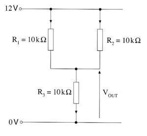
(i) Calculate the combined resistance of the parallel combination R1 and R2.
..............................................................................................................................................
..............................................................................................................................................
[1]
(ii) Calculate the output voltage VOUT.
..............................................................................................................................................
..............................................................................................................................................
[2]
6. Put the three measures of resistance in order of size, starting with the biggest, and ending with the smallest.
kilohm (kΩ)
ohm (Ω)
megohm (MΩ)


[2]
7. Here is a diagram of a resistor R.
Complete the following table.
Resistor Value | Colour of Band 1 | Colour of Band 2 | Colour of Band 3 | Colour of Band 4 |
560Ω | Red | Violet | Red | Silver |
(a) Use the colour code to work out the value of the resistor R.

|
Из за большого объема этот материал размещен на нескольких страницах:
1 2 3 4 5 6 7 8 9 |
