

Партнерка на США и Канаду по недвижимости, выплаты в крипто
- 30% recurring commission
- Выплаты в USDT
- Вывод каждую неделю
- Комиссия до 5 лет за каждого referral
Save your circuit as “E1-Circuits2-Act3”
Complete the following:
When a resistor is connected in series with a bulb, it ______________ the current flowing through the filament.
The larger the value of the resistor, the ______________ the current flowing through the bulb.
Activity 2:
Let us now investigate the use of a potentiometer, set up as a variable resistor to control current flow in a circuit.
2a. Set up the following circuit in your simulator.
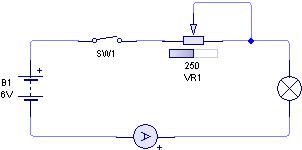
2b. Close the switch then move the slider on the potentiometer by sliding the grey box from left to right. Describe what you observe.
.......................................................................................................................................
.......................................................................................................................................
.......................................................................................................................................
.......................................................................................................................................
Explain this effect : ................................................................................................
.......................................................................................................................................
.......................................................................................................................................
2c. Record the maximum and minimum values of current possible in this circuit.
Minimum Current = .......................... (A, mA, µA)
Maximum Current = .......................... (A, mA, µA)
2d. Connect a voltmeter across the bulb. Move the slider control so that you can measure the following:
Minimum voltage across the bulb = .................... (V, mV, µV)
Maximum voltage across bulb = .................... (V, mV, µV)
Complete the following:
The bulb is at its dimmest when the variable resistor is set to its
.......................................... value.
Save your circuit as “E1-Circuits2-Act4”
Activity 3:
We shall now investigate the use of two resistors in voltage dividing chains.
3a. Set up the following circuit in your simulator. Note that the supply voltage is at 12V.
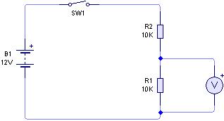
3b. Close the switch and record the voltage provided at the output.
Output voltage = ................. volts
Save your circuit as “E1-Circuits2-Act5”
3c. Open the switch and connect a 6V, 0.06A bulb across the output, as shown below.
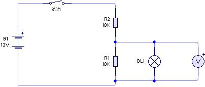
3d. Close the switch, you will probably find that the bulb does not light up. Careful examination of the voltmeter might give you a clue as to why the bulb does not light up.
Voltage across bulb = ................... (V, mV, µV)
Try to explain why the bulb does not light up. This is quite difficult. If you cannot answer ask your tutor for help.
.......................................................................................................................................
.......................................................................................................................................
.......................................................................................................................................
.......................................................................................................................................
.......................................................................................................................................
.......................................................................................................................................
Save your circuit as “E1-Circuits2-Act6”
3e. Switch off the circuit and replace the 10kΩ resistors with 18Ω resistors as shown below.
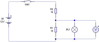
3f. Switch on the circuit and comment on your observations.
.......................................................................................................................................
.......................................................................................................................................
.......................................................................................................................................
.......................................................................................................................................
.......................................................................................................................................
Save your circuit as “E1-Circuits2-Act7”
3g. When the switch is closed - move the mouse over each resistor in turn. If you hold the mouse over the top of the resistor for a few seconds a small information box will appear, which shows you the current flowing through the resistor, and also the power being dissipated.
Which resistor is giving off the most power? .................................................
.......................................................................................................................................
Explain your answer: ...............................................................................................
.......................................................................................................................................
.......................................................................................................................................
.......................................................................................................................................
Information
Resistors can be used to form voltage dividing chains. If current is drawn by a load connected across the chain, the value of the resistors in the chain should be much lower than the load resistor.
Activity 4:
In this activity we shall be investigating the use of a potentiometer for dividing up a voltage.
4a. Set up the following circuit in your simulator. Note that the supply voltage is set to 6V.
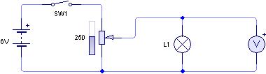
4b. Close the switch then adjust the setting of the potentiometer.
4c. What are the maximum and minimum voltages that can be set across the bulb?
Minimum voltage = ........................... (V, mV, µV)
Maximum voltage = ........................... (V, mV, µV)
What advantage does this circuit have, over that in Activity 2, for controlling the brightness of a bulb?
.......................................................................................................................................
.......................................................................................................................................
Save your circuit as “E1-Circuits2-Act8”
Design Problems:
1. Design a system to provide two levels of intensity from a 6V, 0.06A bulb. The first level gives full intensity, with 6V across the bulb, while the second provides a lower intensity with 4V across the bulb. You have available the following items:

Start by drawing a circuit diagram for the system.
Ask your tutor to check your circuit, and then set it up and try it.
Write a report about how your circuit works.
......................................................................................................................................
......................................................................................................................................
......................................................................................................................................
......................................................................................................................................
.......................................................................................................................................
Save your circuit as “E1-Circuits2-Act9”
2. Design a circuit which will enable you to operate a 6V, 0.06A bulb correctly from a 9V supply. All steps in your calculation must be clearly shown.
You are provided with the following items:

Circuit Diagram:
Calculations:
.......................................................................................................................................
.......................................................................................................................................
.......................................................................................................................................
.......................................................................................................................................
What is your preferred resistor choice 30Ω, 39Ω, 47Ω, 56Ω or 68Ω.
................................
Give a reason for your choice................................................................................
.......................................................................................................................................

|
Из за большого объема этот материал размещен на нескольких страницах:
1 2 3 4 5 6 7 8 9 |
