

Партнерка на США и Канаду по недвижимости, выплаты в крипто
- 30% recurring commission
- Выплаты в USDT
- Вывод каждую неделю
- Комиссия до 5 лет за каждого referral
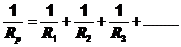
It can be shown that the total or effective resistance Rp of resistors in parallel is given by the general equation:
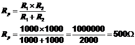
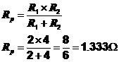
For only 2 resistors in parallel this can be simplified to 
For example,
If R1 = R2 = 1kΩ, (as given in circuit 1) then
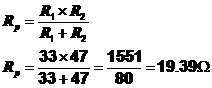
If R1 = 33Ω and R2 = 47Ω (as given in circuit 2) then
Note
1. You should always check you answer when using the formula to make sure that the effective resistance of 2 resistors in parallel is smaller than the individual resistor values.
2. When 2 resistors of the same value are connected in parallel the effective resistance is 1/2 (one half) of their individual values.
3. If 3 resistors of the same value are connected in parallel then the effective resistance is 1/3 (one third) of their individual values. E. g. If three 10k resistors are connected in parallel their effective resistance = 10k/3 = 3.333kΩ.
4. In general if ‘n’ resistors of the same value are connected in parallel then the effective resistance is 1/n (one ‘n’th) of their individual values. E. g. If ‘n’ 10k resistors are connected in parallel their effective resistance = 10k/’n’ Ω.
Worked examples
|
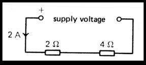
1.
Find
(i) the current in the 2Ω resistor,
(ii) the current in the 4Ω resistor,
(iii) the voltage across the 2Ω resistor,
(iv) the voltage across the 4Ω resistor, and
(v) the supply voltage.
Solution:
(i) 2A (Since this is a series circuit so current is same everywhere)
(ii) 2A (Same reason as (i))
(iii) Apply V = I x R to 2Ω resistor.
V2Ω = 2 x 2 = 4V.
(iv) Apply V = I x R to 4Ω resistor.
V4Ω = 2 x 4 = 8V
(v) Supply voltage V = V2Ω + V4Ω = 4 + 8 = 12V.
2.
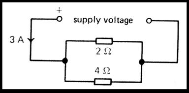
Find (a) the current in the 2Ω resistor,
(b) the current in the 2Ω resistor,
(c) the voltage across the 2Ω resistor,
(d) the voltage across the 4Ω resistor, and
(e) the effective resistance of the parallel circuit.
Solution:
(a) 2A (because the current in the 2Ω resistor will be twice that in the 4Ω resistor.)
(b) 1A (because the current in the 4Ω resistor will be half that in the 2Ω resistor.) Or (Since 3A enters the network, and 2A goes through the other resistor only 1A is left).
(c) Apply V = I x R to 2Ω resistor.
V2Ω = 2 x 2 =4V
(d) Apply V = I x R to 4Ω resistor.
V4Ω = 1 x 4 = 4V Or by inspection V4Ω = 4V since resistors are in parallel and therefore the voltage must be the same as V2Ω.
(e)
3. For the network shown below, calculate:
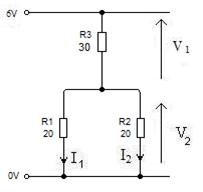
(a) the combined resistance Rp of R1 and R2 in parallel.
(b) the total resistance RT of the network.
(c) I.
(d) V1 and V2.
(e) I1 and I2.
(f) What is the nearest preferred value to RT in the E24 series.
Solution:
(a) Rp = 20W /2 = 10W ( equal resistors in parallel)
(b) RT = R3 + R1 = 10W +30W = 40W
(c) The voltage V across the whole network is 6V and its total resistance RT is 40Ω therefore
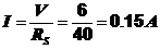
(d) V1 = I x R3 = 0.15A x 30Ω = 4.5V
But V = V1 + V2 therefore V2 = V – V1 = 6 – 4.5 = 1.5V
(e) I1 = I2 = ½I (since R1 = R2) therefore I1 = ½ x 0.15A = 0.075A.
(f) The 2 nearest preferred values to 40W are 39W and 43W so in this case choose 39W.
Summary J
1. Resistors usually exist in combinations of series and parallel components.
2. The effective resistance Rs of series resistors is given by the following formula.

3. The effective resistance Rp of two resistors in parallel is given by the formula.

Homework Questions 1
1. Draw a diagram to show how you would connect two 10Ω resistors to give a total resistance of (a) 20Ω, (b) 5Ω.
(a) (b)
[2]
2. In the circuit below what is
|
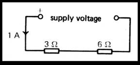
(a) the current in the 3Ω resistor. ……………………… [1]
(b) the current in the 6Ω resistor. ……………………… [1]
(c) voltage across the 3Ω resistor.
…………………………………………………………………………………………………………..……………………………… [2]
(d) voltage across the 6Ω resistor.
…………………………………………………………………………………………………………..……………………………… [2]
(e) the supply voltage.
………………………………………………………………………………………………..………………………………………… [1]
3. In the circuit below, calculate
|
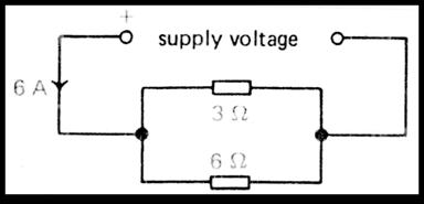
(a) the current in the 3Ω resistor.
………………………………………………………………………………………………..…………………………………… [1]
(b) the current in the 6Ω resistor.
………………………………………………………………………………………………..…………………………………… [1]
(c) the voltage across the 3Ω resistor.
………………………………………………………………………………………………..…………………………………… [1]
(d) the voltage across the 6Ω resistor.
………………………………………………………………………………………………..…………………………………… [1]
(e) the supply voltage.
………………………………………………………………………………………………..…………………………………… [1]
4. For the network shown below calculate the total resistance between
|
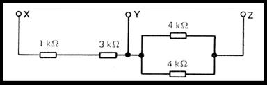
(a) X and Y,
……………………………………………………………………………………………………………
………………………………………………………………………………………………..…………………………………… [1]
(b) Y and Z,
……………………………………………………………………………………………………………
………………………………………………………………………………………………..…………………………………… [1]
(c) X and Z.
……………………………………………………………………………………………………………
………………………………………………………………………………………………..…………………………………… [1]
(d) Use the list of E24 preferred values to select a single resistor to replace the network of 4 resistors.
………………………………………………………………………………………………..…………………………………… [1]
Voltage dividing chains
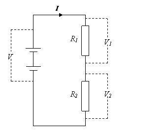
You should remember the Voltage Divider Rule from topic 1.3. It states:
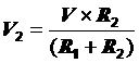
If we connect a load across the output it could change the voltage level set by the resistor chain. If the current taken by the load is greater than 0.1I there will be a significant change in the output voltage.
We will investigate this in the following assignments.
Assignment 1.4A
Investigating resistors
Activity 1:
In this activity you will be investigating the use of resistors to control the current flowing in a circuit.
1a. Set up the following circuit using your circuit simulator.
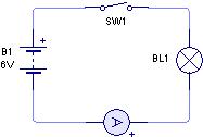
1b. Close the switch. Note the brightness of the bulb, and record the reading from the ammeter.
Brightness : ................................................................................................
Reading on ammeter = ........................... (A, mA or µA)
Save your circuit as “E1-Circuits2-Act1”
1c. Open the switch then modify the circuit so that it has a 100Ω resistor in series with the bulb, as shown below:
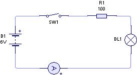
1d. Close the switch. Note the brightness of the bulb, and record the reading from the ammeter.
Brightness : ................................................................................................
Reading on ammeter = ........................... (A, mA or µA)
What effect does the resistor have upon the brightness of the bulb and the current flowing through the filament?
......................................................................................................................................
......................................................................................................................................
......................................................................................................................................
......................................................................................................................................
Save your circuit as “E1-Circuits2-Act2”
1e. Remove the 100Ω resistor and replace it with a 1 kΩ resistor. Close the switch. Note the brightness of the bulb, and record the reading from the ammeter.
Brightness : ................................................................................................
Reading on ammeter = ........................... (A, mA or µA)
Report on any change from 1c.
......................................................................................................................................
......................................................................................................................................
......................................................................................................................................

|
Из за большого объема этот материал размещен на нескольких страницах:
1 2 3 4 5 6 7 8 9 |
