

Партнерка на США и Канаду по недвижимости, выплаты в крипто
- 30% recurring commission
- Выплаты в USDT
- Вывод каждую неделю
- Комиссия до 5 лет за каждого referral
where ![]() is a universal constant called Planck’s constant;
is a universal constant called Planck’s constant; ![]() – wavelength. The numerical value of this constant, to the accuracy known at present, is
– wavelength. The numerical value of this constant, to the accuracy known at present, is

When the light wave cooperates with a molecule it can dissipate, and can be absorbed. Character of dispersion by a single particle depends on the attitude between its radius ![]() and wave length
and wave length ![]() of a scattering light.
of a scattering light.
Depending on size of ![]() it is necessary to distinguish three kinds of dispersion:
it is necessary to distinguish three kinds of dispersion:
1. For the big particles  is observed geometrical scattering. In this case the part of scattering particles is equal:
 , (2)
, (2)
where N – quantity scattering particles, ![]() – length of way on which goes light,
– length of way on which goes light, ![]() – intensity of falling light.
– intensity of falling light.
2. The analysis of dispersion of light for very small particles ![]() has been lead Rayleigh. In this case intensity of a scattered light is proportional to frequency in the fourth power or inversely proportional to wavelength in the fourth power.
has been lead Rayleigh. In this case intensity of a scattered light is proportional to frequency in the fourth power or inversely proportional to wavelength in the fourth power.
 (3)
(3)
3. For particles which sizes are comparable to wave length ![]() the basic is diffraction scattering. The factor of dispersion is defined by the following formula:
the basic is diffraction scattering. The factor of dispersion is defined by the following formula:
 (4)
(4)
In laboratory medical and clinical practice usually use poorly painted solutions of small concentration. For this solutions law of Lambert may be written in form:
 , (5)
, (5)
where ![]() – intensity of falling light,
– intensity of falling light, ![]() – intensity of light past through a solution,
– intensity of light past through a solution, ![]() – coefficient of absorption,
– coefficient of absorption, ![]() – concentration of a solution,
– concentration of a solution, ![]() – thickness of a layer of a solution.
– thickness of a layer of a solution.
Equation (5) often writes in form:
![]() , (6)
, (6)
where ![]() . Using equation (6) we may write:
. Using equation (6) we may write:
 , (7)
, (7)
where ![]() – transparency of solution.
– transparency of solution.
The logarithm of return value:
 (8)
(8)
Value D is called optical density. As ![]() , then
, then
 (9)
(9)
For two solutions with known concentration ![]() and unknown concentration
and unknown concentration ![]() we may write:
we may write:
 and
and ![]() (10)
(10)
Using equations (10) find the ratio![]() :
:
 then
then ![]() (11)
(11)
Expression (11) using for determine unknown concentration painted solutions.
For measurement optical density using special apparatus, this is called the photoelectric colorimeter.

Fig. 1 Photoelectric colorimeter
Order of Carrying Out of the Laboratory Work
1. Open a lid of the apparatus.
2. Switch on the apparatus and wait 15 minutes.
3. Turn a knob “optical filters” (3 on fig. 1) on position «490», the knob “sensitivity” (5 on fig. 1) on position «2».
4. Fill in the first vessel water and place it in a distant compartment inside the apparatus.
5. Fill in the second vessel with a solution (0.2%) and to place it in a near compartment inside the apparatus.
6. Turn a knob to position “1” (4 on fig. 1) and place a vessel with water between a light source and a photosensitive element.
7. Close a lid of the apparatus.
8. Using switches (6 on fig. 1); set a transparency on 100 % position (upper scale).
9. Turn the knob on position “2” and place a vessel with solution between a light source and a photosensitive element.
10. Measure a transparency “T” of a solution.
11. Repeat measurements for the given solution 5 times.
12. Write the results in table 1.
13. Change the solution and carrying-out operations 5-9 for other solutions and measure the transparency and optical density of solution.
14. Write the results in table 2.
15. Draw the graph of dependence of optical densities upon solution concentration.
16. Using this graph, find the value of unknown concentration “X%”.
17. Find the value of unknown concentration “X%”, using formula
![]()
and compare the results.
Table 1
№ | C,% | T,% |
| (T- | (T- | SF |
|
|
1 | ||||||||
2 | ||||||||
3 | ||||||||
4 | ||||||||
5 |
Calculate error of measurement using these formulas:
![]() ; ;
; ;  ;
; ![]() ;
;
![]() - Student’s coefficient, if
- Student’s coefficient, if ![]() and
and  , then
 ![]() ;
;  ;
;
 Table 2
№ | C, % | D | T,% |
1 | |||
2 | |||
3 | |||
4 | |||
5 | |||
X |
18. Write your conclusions.
Laboratory Work №6
Study of Light Diffraction
The aim of this work:
1. To study the theoretical bases of the light diffraction.
2. To determine the wavelength using diffraction grating.
3. To determine grating element.
The equipment:
1. Gratings.
2. Scales.
3. Optical filters.
4. Light source (PRK-2).
Diffraction of Light
Sound is propagated in the form of waves. A sound produced in an adjoining room reaches after bending round the edges of the walls. Similarly waves on the surface of water also bend round the edges of an obstacle and spread out into the region behind it. This bending of waves round the edges of obstacles is called Diffraction and is a characteristic property of waves.
If light is also propagated as wave, it must bend round opaque obstacles placed in its path. Because of the extremely short wave length, the bending of light waves into the shadow of an obstacle is very meager and therefore it is not easily observed. Since the sound waves have a greater wave length the diffraction effects are pronounced. As the wave length of light is very small compared to that of the sound waves and even tiny obstacles have their sizes larger compared to the wavelength of light waves, diffraction effects are so small that light appears to travel along straight line.
Some examples of diffraction pattern:
1. If you keep your middle and the index fingers very close and view a powerful source of light, dark line parallel to your two fingers will appear. These dark lines vanish if the gap is little wider.
2. When you look at the moon through a fine piece of cloth, you could see a row of points of light arranged symmetrically around the brightest central point. Light bends as it passes through the various tiny spaces between the strands of the fabric.
The Dutch scientist Christiaan Huygens (), a contemporary of Newton, proposed a wave theory of light that had much merit. Still useful today is a technique he developed for predicting the future position of a wave front when an earlier position is known. This is known as Huygens' principle and can be stated as follows: Every point on a wave front can be considered as a source of tiny wavelets that spread out in the forward direction at the speed of the wave itself. The new wave front is the envelope of all the wavelets — that is, the tangent to all of them.
As a simple example of the use of Huygens' principle, consider the wave front AB in Fig. 1, which is traveling away from a source S. We assume the medium is isotropic — that is, the speed v of the waves is the same in all directions. To find the wave front a short time t after it is at AB, tiny circles are drawn with radius r – vt. The centers of these tiny circles are on the original wave front AB and the circles represent Huygens' (imaginary) wavelets. The tangent to all these wavelets, the line CD, is the new position of the wave front.
Huygens' principle is particularly useful when waves impinge on an obstacle and the wave fronts are partially interrupted. Huygens' principle predicts that waves bend in behind an obstacle.
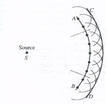
Fig. 1 Huygens’ Principle used to determine wave front CD when AB is given
The bending of waves behind obstacles into the "shadow region" is known as diffraction. Since diffraction occurs for waves, but not for particles, it can serve as one means for distinguishing the nature of light.
Note that the ray model cannot account for diffraction, and it is important to be aware of the limitations of the ray model. Geometric optics using rays is so successful in its limited sphere because normal openings and obstacles are much larger than the wavelength of the light, and so relatively little diffraction or bending occurs.
Fresnel and Fraunhofer Diffraction
Diffraction phenomenon is classified into two groups, i. e. (1) Fresnel diffraction and (2) Fraunhofer diffraction.
In the Fresnel diffraction either a point source or a illuminated narrow slit is used. The source and the screen are at finite distances from the obstacle producing diffraction and no lens is used to focus the rays (Fig. 2). In such case, the wave front undergoing diffraction is either spherical cylindrical.
In the Fraunhofer diffraction the source and the screen are at infinite distances from the obstacle producing diffraction. Hence, in this case the wave front undergoing diffraction is a plane wave front. The rays reaching a point are parallel and are brought to focus by a converging lens (Fig3). These diffracted rays then interfere and produce diffraction patterns known as Fraunhofer diffraction patterns. Fraunhofer diffractions are best observed by a spectrometer.
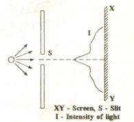
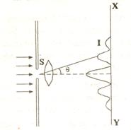
Fig. 2 Fresnel diffraction Fig. 3 Fraunhofer diffraction
Half Period Zones
ABCD is a plane wave front perpendicular to the plane of the paper (Fig. 4) and P is an external point at a distance 'b' perpendicular to ABCD. To find the resultant intensity at P due to the wave front ABCD, Fresnel's method consists in dividing the wave front into a number of half period zones of equal area called Fresnel's zones.
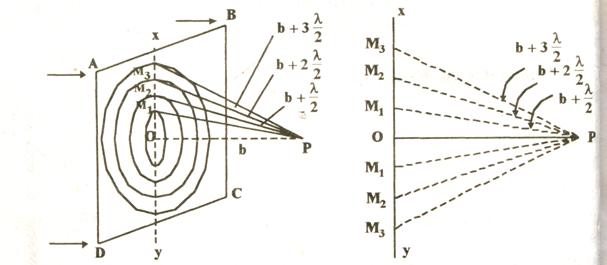
Fig. 4 Half period zones
To find the effect of all the zones at P, with P as centre and radii equal to  etc., construct spheres which will cut out circular areas of radii OM1, OM2, OM3 etc on the wave front. These circular zones are called half period zones.
Each zone differs from its neighbour by a phase difference of n or a path difference of ![]() . Thus the secondary wavelets starting from the point O and Mi reaching P will have a phase difference of π or a path difference of
. Thus the secondary wavelets starting from the point O and Mi reaching P will have a phase difference of π or a path difference of ![]() . These half period zones have equal areas.
. These half period zones have equal areas.
Plane Transmission Grating
A large number of equally spaced parallel slits is called a diffraction grating, although the term "interference grating" might be as appropriate. Gratings can be made by precision machining of very fine parallel lines on a glass plate. The untouched spaces between the lines serve as the slits. Photographic transparencies of an original grating serve as inexpensive gratings. Gratings containing 10,000 lines per centimeter are common today, and are very useful for precise measurements of wavelengths. A diffraction grating containing slits is called a transmission grating. Reflection gratings are also possible; they can be made by ruling fine lines on a metallic or glass surface from which light is reflected and analyzed. The analysis is basically the same as for a transmission grating.
The plane transmission grating is a plane sheet of transparent material on which opaque rulings are made with a diamond point. As many as 6000 rulings are drawn per centimeter width of sheet. The spaces between the rulings are transparent and constitute the parallel slit. The rulings are of equal width and the spaces between rulings are also of equal width. The combined width of a ruling and a slit is called grating element. Points on successive slits separated by a distance equal to the grating element are called corresponding points.
Let ABCDEFG represent the section of a grating normal to the plan of the diagram (Fig. 5) AB, CD, etc. represent the slits of width a, BC, DE, etc. represent the rulings of width b. Now the distance (a+b) or the distance between the two successive slits is called the grating element. Let a plane wavefront be incident normally on the grating. The points in the slits AB, CD, etc. act as secondary source of light giving rise to secondary wavelets which spread in all direction on the other side of the grating. Consider the secondary diffracted wavelets proceeding in a direction which makes an angle G with the normal to the grating.
AGG1 is normal to the direction of diffracted light and therefore represents the diffracted wavefront. Consider the wavelets starting from the corresponding points A and C. The path difference between then on reaching the wavefront AGG1 is CG = AC ![]() .
.
These secondary wavelets travel equal paths beyond AGG1. A convex lens is interposed in the path of the diffracted wavefront. All wavelets from the different slits moving along the same direction are focussed at the same point P. The superposition of these wavelets at P causes interference.
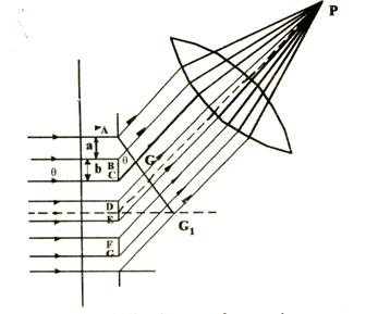
Fig. 5 Diffraction at a plane grating
P will be bright when
![]()
where (m = 0, 1, 2,…)
If  , then
 ![]() i. e. all points in the direction of the incident light will be bright. This is the zero order diffracted image.
i. e. all points in the direction of the incident light will be bright. This is the zero order diffracted image.
If  , then in a direction inclined at an angle
 ![]() to the incident direction, the first order image is obtained; similarly the second order bright image is obtained when
to the incident direction, the first order image is obtained; similarly the second order bright image is obtained when  such that
 ![]() . The different order bright images are obtained on the both sides of the direct ray (Fig. 6).
. The different order bright images are obtained on the both sides of the direct ray (Fig. 6).
When ![]() ; is valid for all colors making the composite light. So the bright bands of all colors are superposed in the undeviated direction. Hence an undispersed white image of the source is obtained.
; is valid for all colors making the composite light. So the bright bands of all colors are superposed in the undeviated direction. Hence an undispersed white image of the source is obtained.
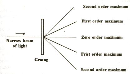
Fig. 6 Diffraction due to a grating
As ![]() increases,
increases, ![]() first passes through
first passes through ![]() values for all colors from violet to red and so darkness results. With further increase of
values for all colors from violet to red and so darkness results. With further increase of ![]() value,
value, ![]() passes through
passes through ![]() values of all colors and so a series of bright images ranging in colors from violet to red (a spectrum) are seen.
values of all colors and so a series of bright images ranging in colors from violet to red (a spectrum) are seen.
In general  is the condition for brightness, where m is an integer
![]()
where  – the number of grating elements or lines per unit width of the grating. In the above discussion the light passes through the grating and hence called transmission grating.
Order of Carrying Out of the Laboratory Work
1. Switch on the device.
2. To get on the screen contrast diffraction picture using the diffraction grating.
3. To determine the wavelength using the following formula: ![]() .
.
4. Put all data in table 1.
Table 1.
Diffraction order maximum | x, mm | l, mm |
|
|
|
|
K=1 | ||||||
K=2 | ||||||
K=3 |
 ·100%
·100%5. Using known values of wavelength determine the diffraction element grating, by following expression expression:

|
Из за большого объема этот материал размещен на нескольких страницах:
1 2 3 4 5 6 7 8 |
